


Our Blog

Spring-Return vs Non-Spring-Return Actuators: Which Do You Need?
The choice between spring-return and non-spring-return actuators is one of the most consequential specification decisions in HVAC and building automation. These two types behave entirely differently when power is cut or a control signal is lost — and specifying the wrong type can result in freeze-damaged coils, failed fire control sequences, or unnecessary capital expenditure across a large installation.
Selection should be driven by the fail-safe requirement of the specific application — not by habit, default specifications, or cost alone. To make the correct choice, you must understand what happens to the connected damper or valve when power is lost, and whether that outcome is acceptable given the system, its occupants, and the applicable Australian Standards. This guide sets out the technical differences, code obligations, and a practical decision framework for the most common HVAC applications.
How Spring-Return Actuators Work
A spring-return (SR) actuator uses an electric motor to drive a gear train that rotates the output shaft — and simultaneously compresses an internal coil spring. When the motor is de-energised (power removed, or control signal lost), the compressed spring releases and drives the shaft back to its starting, or fail-safe, position.
Spring-return actuators are available in two fail-safe configurations, which must be specified at time of order:
- Normally-closed (NC): the spring drives the shaft to the closed position (0°). The motor is energised to open the actuator. On power loss, the actuator closes.
- Normally-open (NO): the spring drives the shaft to the open position (90°). The motor is energised to close the actuator. On power loss, the actuator opens.
The fail-safe position is set at manufacture and cannot be reversed in the field. Always specify NC or NO on the purchase order. An important operational characteristic of spring-return actuators is that they draw continuous electrical power at any intermediate modulating position — the motor must continuously counteract the spring force to hold the shaft at positions other than the fail-safe position.
How Non-Spring-Return Actuators Work
A non-spring-return (NSR) actuator uses an electric motor to drive a self-locking worm gear that positions the output shaft. When the motor stops, the worm gear holds the shaft in position without any motor power — the worm gear geometry prevents back-driving, so air pressure, valve pressure, and gravity cannot move the shaft. On power loss, the result is hold-in-last-position: the shaft remains exactly where it was when power was cut.
Electronic fail-safe (capacitor-return) actuators exist as a variant that offers some of the size and power efficiency advantages of NSR actuators while providing a defined fail-safe position. These actuators store energy in an internal capacitor and, on power loss, use that stored energy to drive to a pre-programmed position. However, this approach relies entirely on the capacitor being functional — periodic testing and capacitor replacement are required to maintain the fail-safe behaviour, and capacitor-return actuators are not to be used in life-safety applications where spring-return is mandated by Australian Standards. For life-safety applications, mechanical spring-return remains the only compliant option.
The power draw of an NSR actuator holding position is less than 0.5 W, compared to 2–5 W continuously for a spring-return actuator holding an intermediate modulating position. In large installations with many actuators, this energy difference is measurable over a year of operation.
Comparing the Two Types
| Feature | Spring-Return | Non-Spring-Return |
|---|---|---|
| Fail-safe position | Defined at manufacture (open or closed) | Holds last position (or programmable with capacitor — see note) |
| Code requirement for life-safety | Mandatory (fire/smoke dampers, OA dampers) | Not acceptable for life-safety applications |
| Operating power draw | Higher — motor continuously counteracts spring | Lower — worm gear holds position without motor power |
| Physical size for same torque | Larger — spring housing adds bulk and mass | More compact |
| Capital cost | Higher (typically 30–60% above equivalent NSR) | Lower |
| Mechanical life | Spring fatigue over time; check manufacturer cycle rating | Longer mechanical life in most applications |
| Manual override | Most include pushbutton or hex key override | Most include a manual override |
When Spring-Return Is Required
Spring-return actuators are not an option in applications where a defined fail-safe position is required by Australian Standards or by the consequences of the application. Understanding these requirements before specifying is essential.
Fire and smoke dampers (AS 1668.1, AS 1851): Spring-return is mandatory for all fire and smoke damper actuators. The actuator must drive to the closed position on loss of electrical power or on a trip signal from the fire control panel. Non-spring-return actuators — including capacitor-return variants — are not compliant for this application. Auxiliary switch outputs providing proof-of-closure contacts are also required; confirm the switch configuration (normally-open or normally-closed contact, and the voltage and current rating) against the fire control panel specification before ordering.
Outdoor air dampers in most Australian applications: AS 1668.2 cold-air protection requirements and standard engineering practice require OA dampers to close on power loss in virtually all Australian commercial HVAC applications. This includes temperate climate zones such as Adelaide, Melbourne, and Canberra, where winter temperatures create freeze risk for chilled water coils and heating coils. Spring-return NC is the correct specification for OA damper actuators across the overwhelming majority of Australian commercial projects.
Beyond code obligations, spring-return should also be specified in any application where the consequence of the actuator failing to reach a defined position is operationally significant — including applications where the BMS cannot guarantee a prompt command to the actuator following power restoration, valves on high-pressure steam or high-temperature hot water circuits where an open valve during power failure would be hazardous, and applications in buildings where the BMS has a history of losing control of actuators during power disturbances.
When Non-Spring-Return Is Acceptable
VAV box primary air dampers in most commercial buildings: Hold-in-last-position is acceptable for the primary air damper in a standard VAV terminal unit in commercial office, retail, or education applications. The majority of VAV actuator installations in Australian commercial buildings use NSR actuators. Belimo LM series and Siemens SAS series both offer NSR variants specifically suited to VAV terminal mounting. Where the project specification or brief explicitly requires spring-return on VAV boxes — for example, for specific critical-environment zones — spring-return must be used; but it is not the default requirement for commercial VAV applications.
Modulating mixing box dampers in mild climates: Where freeze protection of coils is not a concern and the system includes independent safeguards (such as a low-limit temperature controller), an NSR actuator on a mixing box return-air or relief-air damper may be acceptable. This requires a documented fail-safe analysis and sign-off from the mechanical engineer responsible for the project — it is not a blanket permission.
Cost-constrained applications with appropriate fail-safe analysis: Where capital cost is a significant project constraint and the application is not life-safety critical, a structured fail-safe analysis demonstrating that hold-in-last-position is an acceptable outcome can support the use of NSR actuators. The analysis must be documented, reviewed by the responsible engineer, and retained as part of the project record.
Interior supply and return air dampers with no life-safety function and no freeze risk: Balancing dampers, zone isolation dampers, and similar interior air-distribution components where the fail-safe position is genuinely immaterial — where neither fully open nor fully closed creates a safety or significant comfort concern — are appropriate candidates for NSR actuators.
Energy and Cost Considerations
Spring-return actuators draw 2–5 W continuously when holding at intermediate modulating positions. For a large installation, this adds up: a building with 200 modulating spring-return actuators averaging 4 W continuous power draw over 8,760 hours per year consumes approximately 7,008 kWh annually. At a commercial electricity rate of $0.25/kWh, this represents around $1,750 per year in electricity costs attributable to actuator holding power — before factoring in cooling load on the air conditioning system.
NSR actuators draw less than 0.5 W holding position. The same 200 actuators consume approximately 875 kWh per year — a reduction of more than 85%. For large projects where NSR actuators are technically appropriate, this energy difference is a meaningful lifecycle cost consideration.
Capital cost differences are equally real. Spring-return actuators typically cost 30–60% more than equivalent NSR models for the same torque output and control type. On a project with many actuators, the capital premium for spring-return over NSR can be substantial — and is only justified where the fail-safe requirement genuinely demands it. Blanket specification of spring-return for applications where NSR is technically acceptable increases project cost without improving system safety or performance.
Spring fatigue over the actuator's service life is a consideration for lifecycle planning. Manufacturers typically rate spring-return actuators for 60,000–100,000 full cycles. An OA damper cycling once per occupied hour accumulates approximately 3,000 cycles per year — implying a spring life of 20–33 years under normal occupied-building conditions. Applications with higher cycle rates, such as demand-controlled ventilation with frequent CO₂-driven resets, will experience spring fatigue sooner. Include planned spring and actuator replacement in the lifecycle maintenance plan for all critical and life-safety applications, as required by AS 1851.
Belimo and Siemens Options from Controls Traders
Belimo spring-return variants are identified by the "SR" suffix in the model number (for example, LM24A-SR is the spring-return variant of the LM24A NSR model). This convention applies consistently across the LM, NM, AM, and GM series for damper actuators, and across the valve actuator ranges. NSR models incorporate the mechanical self-locking worm gear that holds position without motor power and cannot be back-driven by air pressure or fluid pressure. Browse the full Belimo product range or see the Belimo model numbers guide for a complete breakdown of the model number structure.
Siemens offers both SR and NSR variants across the SSA series (3–45 Nm, AHU and general HVAC damper applications) and the SAS series (purpose-designed for VAV terminal unit mounting). As with Belimo, the spring-return variants are distinguished by specific model number suffixes — refer to the Siemens actuator series guide for model selection guidance, or browse the Siemens product range on the Controls Traders website.
Contact the Controls Traders team for specification support, fail-safe analysis guidance, or to confirm stock availability for project programmes.
Practical Decision Guide
Use this guide as a starting point for each application on a project. In all cases, the responsible mechanical or controls engineer must confirm the fail-safe analysis for the specific application before ordering.
- OA damper, AHU application: spring-return NC. In virtually all Australian applications, without exception.
- Fire/smoke damper: spring-return NC. Mandatory per AS 1668.1 and AS 1851. No alternative.
- Relief/exhaust damper: spring-return NO or NSR depending on system design and fail-safe analysis — confirm with mechanical engineer.
- VAV box primary air damper: NSR acceptable in most commercial applications. Specify spring-return NC where the project brief or specification requires it, or where the application makes holding-last-position unacceptable.
- Chilled water coil valve (2-way): spring-return fail-closed (NC) is standard; for heating coils and some process applications, confirm the required fail-safe direction — fail-open (NO) is specified in some heating coil applications to prevent overheating.
- Low-risk interior supply/return air damper: NSR acceptable where hold-in-last-position is not a safety or comfort concern.
- Any life-safety or code-driven application: spring-return required. Confirm fail-safe direction (NC or NO) and auxiliary switch requirements against the applicable Australian Standard before ordering.
Frequently Asked Questions
Is a spring-return actuator required for all outdoor air dampers?
In Australian commercial HVAC, spring-return normally-closed (NC) actuators are required for outdoor air dampers in virtually all applications. When the AHU shuts down, the OA damper must close to prevent uncontrolled cold outdoor air reaching chilled water or refrigerant coils (freeze risk), and to prevent uncontrolled building pressurisation or air quality degradation. AS 1668.2 cold-air protection requirements and standard engineering practice both support this requirement. The only scenario where a fail-safe analysis might support an NSR actuator is in a mild climate with no freeze risk and independent safeguards — this requires documented engineering sign-off and is not a general exception.
Can I use a non-spring-return actuator for a fire or smoke damper?
No. AS 1668.1 and AS 1851 require fire and smoke damper actuators to be spring-return with a fail-safe close on loss of electrical power or fire control panel signal. Non-spring-return actuators hold their last position on power loss and are not compliant for this application — a damper at 50% open on power loss remains at 50% open, which does not satisfy the requirement to close on fire signal. Life-safety damper actuators also require auxiliary switch outputs providing proof of damper closure to the fire control panel, which must be confirmed on the actuator specification before ordering.
What is "hold-in-last-position" and when is it appropriate?
Hold-in-last-position (HILP) is the fail-safe behaviour of a non-spring-return actuator — on loss of power or control signal, the worm gear self-locks and the actuator shaft remains in its last commanded position. This is appropriate when the consequence of maintaining that position is acceptable for the application: a VAV box damper that stays at 50% open on a brief power outage continues delivering approximately 50% of design airflow until power is restored, which is typically not a safety concern in commercial offices. It is not appropriate when the fail-safe requirement is a defined position — fully open or fully closed — regardless of the actuator's last commanded position before the power loss.
Spring-return actuators cost more. Can I reduce cost by using NSR actuators where spring-return is specified?
Only where the fail-safe analysis for that specific application supports the substitution. Replacing spring-return with NSR without reviewing the fail-safe analysis risks non-compliance with AS 1668.1 for life-safety dampers, freeze damage to coils on OA damper applications, or loss of the intended system protection. The cost saving is real — spring-return actuators typically cost 30–60% more than equivalent NSR models — but the decision must be made by the responsible mechanical or controls engineer after reviewing the application requirements, not made generically to reduce project cost without engineering assessment.
How long does the spring last in a spring-return actuator?
Manufacturers typically rate spring-return actuators for 60,000–100,000 full cycles, where one cycle equals one complete open-to-close-and-return stroke. For an OA damper that cycles once per hour during occupied hours — approximately 3,000 cycles per year assuming a 250-day occupied year with 10-hour occupied periods — this represents a rated spring life of 20–33 years under normal conditions. For more frequently cycling applications such as modulating demand-controlled ventilation where the actuator may cycle several times per hour, the spring life shortens accordingly. Check the manufacturer's published cycle rating for the specific model, and include spring and actuator replacement in the lifecycle maintenance plan for critical and life-safety applications in accordance with AS 1851.

BAPI CO2, Humidity and Temperature Sensors: A Product and Selection Guide
Building Automation Products Inc. (BAPI) manufactures a comprehensive range of sensors for HVAC and building automation applications. The BAPI sensor line covers CO₂, relative humidity, temperature, and combinations of all three parameters — in wall-mount, duct-mount, and outdoor configurations suitable for the full range of commercial and industrial building environments. The range is designed specifically for integration with Building Automation Systems (BAS), with output options to suit both analogue BMS inputs and digital field buses including BACnet MS/TP and Modbus RTU.
Controls Traders is an authorised Australian distributor of BAPI products, supplying the sensor range to mechanical contractors, building automation integrators, and consulting engineers across South Australia and nationally. This guide covers the BAPI sensor product categories, configuration options, output types, accuracy specifications, installation requirements, and selection guidance for common HVAC and BAS applications.
BAPI Sensor Product Categories
The BAPI range is structured around parameter combinations and mounting configurations, allowing engineers and BAS integrators to select the minimum sensor complexity needed for each application. The primary product categories are:
| Sensor Type | Parameters Measured | Available Mounting | Typical Application |
|---|---|---|---|
| CO₂ only | CO₂ concentration (ppm) | Wall, duct | Demand-controlled ventilation (DCV), CO₂ monitoring |
| CO₂ + temperature | CO₂ (ppm), temperature (°C) | Wall, duct | Zone control with DCV, replace two separate sensors |
| CO₂ + relative humidity | CO₂ (ppm), relative humidity (%RH) | Wall | IAQ monitoring where temperature is measured separately |
| CO₂ + RH + temperature | CO₂ (ppm), relative humidity (%RH), temperature (°C) | Wall | Full zone IAQ sensor — single device, all parameters |
| Humidity + temperature | Relative humidity (%RH), temperature (°C) | Wall, duct, outdoor | AHU humidity control, outdoor enthalpy measurement, zone monitoring |
| Temperature only | Temperature (°C) | Wall, duct, immersion, outdoor | Zone and duct temperature sensing, pipe immersion measurement |
Combination sensors deliver a meaningful installation efficiency advantage: where CO₂, humidity, and temperature are all needed in a single zone, one combination sensor requires one mounting location, one conduit entry, and — if using a digital output — a single pair of signal conductors carrying all three parameters to the BMS. This compares favourably with three separate sensors requiring three mounting locations, three conduit entries, and three sets of analogue wiring.
CO₂ Measurement — NDIR Technology
BAPI CO₂ sensors use Non-Dispersive Infrared (NDIR) sensing technology — the HVAC industry standard for CO₂ measurement. The NDIR cell passes infrared light through a sample chamber; CO₂ molecules absorb radiation at a characteristic wavelength of 4.26 μm. The ratio of the absorbed signal to a simultaneously measured reference signal (at a wavelength not absorbed by CO₂) is processed by the sensor electronics and converted to a CO₂ concentration reading in parts per million (ppm). A two-channel measurement approach compensates for gradual degradation of the infrared source over the sensor's service life, maintaining accuracy without requiring frequent external calibration.
BAPI CO₂ sensors incorporate automatic temperature compensation to maintain accuracy across the installation environment temperature range typical of wall-mount occupied space and duct applications. Without temperature compensation, the thermal expansion of gases in the NDIR sample chamber would introduce a systematic error as ambient temperature varies across the operating range — a particularly relevant consideration for duct sensors installed in AHU return sections where air temperature may vary seasonally.
Typical BAPI CO₂ sensor specifications:
- Measurement range: 0–2,000 ppm (standard HVAC DCV range) or 0–5,000 ppm (extended range for higher-occupancy or safety-monitoring applications)
- Accuracy: ±50 ppm ± 3% of reading at calibration temperature
- Automatic Baseline Calibration (ABC): 7-day or 14-day cycle, field-selectable on many models
- Manual calibration: Available on most models via a calibration port for zero and span adjustment using reference gas — necessary for continuously occupied spaces where ABC cannot function correctly
- Warm-up time: Typically 2–5 minutes to stable reading after power-up
ABC is effective for the majority of commercial building applications where the monitored space is regularly unoccupied. For continuously occupied environments — certain healthcare facilities, 24-hour operations centres, or manufacturing spaces — manual calibration against 400 ppm reference gas should be scheduled on an annual basis. Record calibration dates and readings in the asset management system or BMS historian.
Relative Humidity Measurement
BAPI humidity sensors use a capacitive polymer sensing element — the industry-standard technology for HVAC-grade humidity measurement. A thin polymer film changes its dielectric constant in proportion to the relative humidity of the surrounding air; the resulting change in capacitance is measured electronically and converted to a percentage relative humidity (%RH) reading. Capacitive polymer sensors are well-suited to commercial HVAC applications: they respond reasonably quickly to humidity changes, recover well from brief condensation events (assuming the condensation clears), and maintain accuracy across the 0–95% RH range encountered in occupied building environments.
Typical specifications for BAPI capacitive humidity sensors:
- Measurement range: 0–100% RH (non-condensing)
- Accuracy: ±3% RH at 25°C across the 10–90% RH range (typical; may be slightly reduced at extremes near 0% or 100% RH)
- Operating temperature range: 0–60°C for duct sensors; 0–50°C for wall-mount sensors
- Response time: Typically 30–60 seconds to 90% of step change in humidity (sensor-dependent)
An important application note for BAPI humidity sensors — and capacitive polymer sensors generally: these sensors are susceptible to contamination from high concentrations of volatile organic compounds (VOCs). Prolonged exposure to elevated VOC concentrations can cause the polymer film to absorb contaminants, leading to a permanent offset error in the humidity reading that cannot be corrected by recalibration. For most commercial HVAC applications — offices, retail, educational facilities, healthcare — this is not a concern. In spaces with regular solvent-based cleaning operations, paint spray booths, laboratories with organic solvent use, or industrial processes generating high VOC loads, confirm sensor suitability with the specifying engineer before installation. In those environments, BAPI or the Controls Traders technical team can advise on appropriate sensor selection or placement strategies to minimise exposure.
Temperature Measurement
BAPI temperature sensors are available with thermistor (NTC) or platinum RTD (PT100, PT1000) sensing elements, with the choice depending on the application accuracy requirements, cable run length, and BMS input type.
Thermistor (NTC) elements — typically 10 kΩ NTC — are the most common choice for wall-mount room temperature sensors in commercial BAS applications. The 10k NTC characteristic is supported natively by virtually all BMS platforms as a standard universal input type, and the passive thermistor output requires no sensor power supply (the BMS provides a small excitation current). NTC thermistors provide good sensitivity across the typical occupied space temperature range of 15–35°C, with accuracy generally better than ±0.5°C when the BMS input is correctly characterised to the thermistor curve. For longer cable runs — typically above 30–50 m — the cable resistance relative to the thermistor impedance becomes a source of measurement error; in these cases, an active 4-20 mA or 0-10 V output is preferred.
Platinum RTD elements (PT100 or PT1000) offer higher accuracy and better linearity across a wider temperature range than NTC thermistors, and are typically specified for duct and immersion sensors where temperatures may extend below 0°C or above 60°C, or where measurement accuracy better than ±0.5°C is required. PT1000 elements are generally preferred over PT100 for HVAC applications because the higher base resistance (1,000 Ω vs 100 Ω at 0°C) reduces the relative contribution of cable resistance to measurement uncertainty.
Active temperature sensor outputs (4-20 mA or 0-10 V, requiring 24 VAC/DC supply) are available on BAPI combination sensors, and are recommended for cable runs exceeding approximately 50 m, or where the sensor is installed in high-electrical-noise environments such as plant rooms with variable-speed drives.
Output Options and BMS Integration
BAPI sensors are available with a range of output options to match the input types and field bus architecture of the building automation system. Selecting the correct output at the time of order is important — most BAPI sensors are configured at the factory for a specific output type, and field conversion between output types is not generally supported.
| Output Type | Signal | Typical Use Case |
|---|---|---|
| Analogue voltage | 0–5 V or 0–10 V | BMS analogue input, cable runs under 30 m in low-noise environments |
| Analogue current | 4-20 mA | BMS analogue input, longer cable runs, electrically noisy plant rooms |
| BACnet MS/TP | Digital RS-485 | Direct BMS field bus integration; multiple parameters on single two-wire bus |
| Modbus RTU | Digital RS-485 | Modbus-compatible controllers, data loggers, energy metering systems |
| Passive thermistor | 10k NTC resistance | Temperature-only sensing via BMS universal input (no power supply required) |
For combination sensors measuring CO₂, humidity, and temperature in a single housing, BACnet MS/TP or Modbus RTU outputs are strongly recommended over analogue. With analogue outputs, each parameter requires a dedicated pair of conductors, a dedicated BMS analogue input channel, and individual scaling and engineering unit configuration. With a digital output, all three parameters are transmitted over a single screened twisted-pair bus, with each parameter appearing as a separate object or register in the protocol. This can reduce field wiring by 60–70% in multi-sensor installations and simplifies BMS commissioning. For guidance on selecting between BACnet MS/TP and Modbus RTU for your specific BMS architecture, see our article on BACnet vs Modbus (link to be added when article is published).
Installation — Wall-Mount Sensors
BAPI wall-mount sensors are designed to mount on a standard electrical backbox. The sensor uses a two-part assembly: a base plate that fixes to the backbox and accepts the field wiring via a removable terminal block, and a sensor head that clips onto the base. This design has a practical maintenance advantage — the sensor head can be removed for servicing, replacement, or temporary relocation without disturbing the field wiring, which remains connected to the base terminal block.
Correct placement is critical to the accuracy of wall-mount zone sensors. The following guidelines apply across all parameter types:
- Mounting height: 1.2–1.5 m above finished floor level. This corresponds to the breathing zone for seated occupants (for CO₂) and provides a representative zone temperature measurement not influenced by floor-level cold air pooling or ceiling-level heat stratification.
- Distance from supply diffusers: Minimum 300 mm — supply air will locally dilute CO₂ and depress the temperature and humidity reading. In high-throw diffuser arrangements or where the sensor is below a linear slot diffuser, increase this clearance.
- Distance from return air grilles: Minimum 600 mm — CO₂ concentration is locally elevated adjacent to return grilles as air is drawn in from across the zone.
- Distance from operable windows, external doors, or exterior walls: Minimum 1 m — infiltration of outdoor air will depress CO₂ and affect temperature and humidity readings in ways not representative of the general zone condition.
- Avoid direct sunlight: Solar radiation on the sensor housing will cause the temperature measurement to read above actual zone air temperature due to radiant heat gain on the housing surface.
- Avoid dead-air corners and above heat-generating equipment: Poor air circulation locations will not provide readings representative of the occupied zone.
Installation — Duct-Mount Sensors
BAPI duct sensors mount through a circular penetration (typically 32 mm diameter) in the duct wall, secured with a flanged housing and self-tapping screws into the duct sheet metal. The sensing probe extends into the duct airstream. Access for installation and maintenance requires a clear working space adjacent to the duct penetration — confirm that the selected mounting location is accessible after the duct is insulated, and that any insulation jacket can be locally removed and reinstated without damaging the sensor wiring.
Application-specific mounting location guidance:
- CO₂ duct sensors for DCV: Mount in the return air duct section — downstream of the last zone return connection to the return air riser, but upstream of any outdoor air mixing point. This ensures the sensor reads the blended zone return air, not diluted mixed air.
- Humidity sensors in AHU applications: Mount in a well-mixed section of the airstream. For supply humidity control, locate downstream of the cooling coil and reheating elements where supply air conditions have stabilised. For return air sensing (enthalpy economiser or space humidity control), locate in the main return air duct where mixing from all return branches is complete.
- Temperature sensors: Mount sufficiently downstream of any air mixing point, damper, or coil to ensure the duct cross-section is well-mixed. Single-point sensors in large ducts may not represent the average duct temperature if there are significant temperature gradients — multi-point averaging elements are available for large duct cross-sections where accuracy is critical.
Verify duct air velocity at the installation point against the sensor's rated maximum. Most BAPI duct sensors are rated for airstream velocities up to 10–15 m/s. At velocities above this, mechanical fatigue of the probe and errors from velocity pressure effects on the sensing element may reduce long-term reliability and accuracy. At very low velocities (below 0.5 m/s), response time may be extended due to limited convective airflow past the sensing element.
BAPI Sensor Selection Guide
The following selection logic covers the most common HVAC and BAS applications for BAPI sensors. Confirm output type compatibility with the BMS analogue input or field bus architecture before placing an order — this is the most common source of ordering errors and cannot be corrected in the field without sensor replacement.
- CO₂-only DCV control: Select a CO₂ wall or duct sensor with analogue output (4-20 mA for runs over 30 m; 0-10 V for shorter runs). One sensor per independently controlled zone or AHU return duct.
- Zone DCV with thermostat function: Select a CO₂ + temperature combination wall sensor. The single device replaces a standalone CO₂ sensor and a separate room temperature sensor, reducing both hardware cost and installation time.
- Full zone IAQ monitoring (CO₂, humidity, temperature): Select a three-in-one combination wall sensor. Specify BACnet MS/TP or Modbus RTU output to minimise wiring and analogue input consumption. This is the recommended configuration for Green Star or NABERS IAQ-monitored zones where all three parameters must be logged continuously.
- AHU supply or return humidity control: Select a duct humidity + temperature sensor with analogue output. Confirm duct velocity at the installation point and select a model rated for the expected velocity range.
- Outdoor air enthalpy calculation: Select an outdoor-rated humidity + temperature sensor with analogue or digital output. Confirm the sensor's outdoor temperature rating covers the full range expected at the site — for exposed locations in climate zones with sub-zero winter conditions, confirm the lower operating temperature limit.
- Modbus-based systems: Select Modbus RTU output variants across all sensor types. Confirm the Modbus register map with the BMS integrator before ordering — register addresses, data formats (16-bit integer vs floating point), and scaling factors must match the controller's expectations.
For applications not covered by the above, or where there is uncertainty about the correct BAPI product for a specific BMS input type or protocol configuration, contact Controls Traders for technical selection support. The Controls Traders team can advise on current BAPI product availability, lead times for non-stock configurations, and compatibility with major BMS platforms installed in the Australian market.
Frequently Asked Questions
Should I use a combination CO₂/RH/temperature sensor or separate sensors?
A combination sensor in a single housing reduces installation time and wiring cost, and avoids the problem of parameters being measured at different locations in the zone — which can introduce inconsistencies in data interpretation. Where CO₂, humidity, and temperature all need to be monitored in a given zone, a combination sensor is typically the better choice for both cost and data quality reasons. Use separate sensors only when different parameters genuinely need to be measured at different locations — for example, a duct humidity sensor at the AHU to control supply humidity, combined with a wall CO₂ sensor in the occupied zone for DCV. A combination sensor in that scenario would measure supply duct conditions for humidity and zone conditions for CO₂, which are incompatible measurement requirements.
What BAPI sensor should I use for a multi-zone VAV system?
For individual zone control in a VAV system, wall-mount CO₂ sensors in each zone with 0-10 V or 4-20 mA output to the local VAV controller are the standard approach — the zone controller reads CO₂ and adjusts the VAV damper position directly. Where the BMS is managing DCV centrally rather than at the zone controller level, BACnet MS/TP sensors reduce analogue input count significantly: each sensor appears as a BACnet device on the RS-485 field bus, and the BMS reads CO₂ (and temperature and humidity if present) as standard BACnet Analogue Input objects. Contact Controls Traders for advice on the best BAPI model for your specific zone controller type and BMS platform.
How do I wire a BAPI CO₂ sensor to a BMS?
For analogue voltage output sensors (0-10 V), three conductors are needed: 24 VAC/DC power supply positive, signal output (wired to BMS analogue input channel), and power/signal common. For 4-20 mA two-wire loop-powered sensors, only two conductors are needed — the supply and the return, which carries the current signal; the BMS analogue input provides the loop supply voltage. For BACnet MS/TP or Modbus RTU sensors, use a screened twisted-pair cable for the RS-485 bus, connecting data (+), data (−), and cable screen to the sensor terminal block. Observe bus termination requirements: terminate the RS-485 bus at both physical ends with the specified termination resistor value (typically 120 Ω), and ensure all devices on the bus share a common reference (signal ground). Confirm addressing requirements — BACnet MS/TP devices require unique MAC addresses in the range 1–127 for field devices, while Modbus RTU devices require unique slave addresses in the range 1–247.
What is the accuracy of BAPI humidity sensors?
BAPI capacitive polymer humidity sensors are typically rated at ±3% RH accuracy at 25°C across the 10–90% RH range. At the extremes of the measurement range — below 10% RH or above 90% RH — accuracy may be slightly reduced, though these extremes are rarely encountered in normal commercial HVAC operation. In practice, HVAC humidity control setpoints are typically 40–60% RH for comfort control and 30–65% RH for IAQ compliance, well within the range where ±3% RH accuracy is fully maintained. For critical process applications requiring tighter humidity accuracy — pharmaceutical cleanrooms, certain laboratory environments — confirm with Controls Traders whether a higher-accuracy sensor grade is appropriate.
Does BAPI support BACnet?
Yes. BAPI offers BACnet MS/TP (RS-485 physical layer) as an output option across their range of combination and standalone CO₂, humidity, and temperature sensors. BACnet MS/TP sensors connect to the BMS's RS-485 field bus alongside other BACnet field devices, with each sensor appearing as a BACnet device presenting Analogue Input objects for each measured parameter — CO₂ concentration, relative humidity, and temperature as applicable. BAPI also offers Modbus RTU output as an alternative for systems using Modbus-based controllers, sub-meters, or data loggers where BACnet is not available or where the system integrator prefers Modbus. Confirm the required protocol and output configuration with Controls Traders before ordering, as factory configuration is required for digital output variants.

Damper Actuators for AHUs and VAV Systems: Selection and Sizing Guide
Damper actuators convert an electrical control signal into a mechanical rotation to position an air damper blade or array. In an air handling unit, damper actuators control the mix of outdoor, return, and relief air — determining how much conditioned return air is recirculated and how much fresh outdoor air is introduced. In a VAV system, they modulate the primary air damper within each terminal unit to regulate supply airflow to each zone. Selecting the correct actuator — in terms of torque output, spring-return requirement, and control signal type — is fundamental to reliable system operation across the life of the building.
The consequences of poor actuator selection are concrete and costly. An undersized actuator cannot develop sufficient torque to fully close a damper against system static pressure, allowing uncontrolled air leakage and rendering the control sequence ineffective. An oversized actuator on a lightweight VAV damper blade may distort the shaft or blade over time. Incorrect fail-safe selection — specifying a non-spring-return actuator where spring-return is required — creates freeze risk on chilled water coils and hot water coils in cold climates, or ventilation failures that may breach AS 1668.2 requirements. The guidance below covers the selection and sizing process for the most common Australian commercial HVAC applications.
Types of Damper Actuators in HVAC
Damper actuators are broadly categorised by their control signal type and by whether they include a spring-return fail-safe mechanism. The table below summarises the main types and their typical applications in commercial HVAC.
| Actuator Type | Spring Return | Fail-Safe | Typical Applications |
|---|---|---|---|
| On/off (2-position), spring return | Yes | Closes or opens on power loss | OA dampers, exhaust/relief dampers, smoke dampers |
| Floating (3-point), spring return | Yes | Yes | VAV boxes, mixing boxes, smaller AHU dampers |
| Modulating (0–10V or 4–20mA), spring return | Yes | Yes | OA dampers on AHUs requiring proportional control, mixed-air control |
| Modulating, non-spring return | No | Holds last position | VAV boxes, supply/return dampers where fail-safe is hold position |
| Smoke/fire rated | Yes (spring return) | Mandatory fail-safe | Fire/smoke dampers per AS 1668.1 |
Note: This article focuses on damper actuators for air-side control. For valve actuators on chilled water, hot water, or steam services, see the related guide to Siemens actuator series.
AHU Damper Applications
Outdoor air (OA) damper: The OA damper modulates or positions to control the volume of outdoor air entering the AHU. In most climate-controlled Australian buildings, the OA damper must fail closed — closing on loss of power prevents uncontrolled introduction of cold outdoor air in winter (freeze risk on chilled water coils and heating coils) and hot, humid air in summer. A spring-return actuator in the normally-closed (NC) configuration is required. The motor is energised to open the damper; on power loss, the spring drives it closed. AS 1668.2 minimum outdoor air requirements must still be achieved when the system is operational — the spring-return fail-safe addresses shutdown conditions only.
Return air (RA) damper: In an AHU with a mixing box, the return air damper is typically modulated in opposition to the OA damper — as the OA damper opens, the RA damper closes proportionally, and vice versa. The fail-safe direction depends on system design. A normally-open (NO) spring-return configuration (spring drives to fully open on power loss) is common, as it ensures return air continues to flow and prevents excessive negative pressure in the building when the AHU trips.
Relief and exhaust dampers: Provide a pressure relief path for excess supply air when the OA damper opens significantly. A normally-open (NO) spring-return actuator is frequently specified so that the building can relieve pressure even when the relief path control fails. Confirm the required fail-safe direction with the system designer based on the building pressurisation strategy.
Smoke and fire dampers: Actuators for smoke and fire dampers must comply with AS 1668.1 and AS 1851. Spring return to the closed position is mandatory — there is no alternative. Actuators must also provide auxiliary switch feedback (proof of closure) for fire control panel integration. Some dampers use a fusible link release mechanism rather than an actuator for thermal actuation — confirm the specification with the fire engineer before ordering.
VAV Box Damper Applications
A VAV terminal unit uses a single modulating actuator to position the primary air damper blade, typically a round damper within a circular duct section of 100–400 mm diameter. The control sequence is straightforward: as zone temperature rises above cooling setpoint, the VAV controller opens the primary air damper to increase cold supply airflow. As the zone reaches setpoint, the damper closes toward its minimum position, which must maintain minimum ventilation air rates per AS 1668.2. Actuators that do not reliably drive to the minimum position risk ventilation non-compliance.
The fail-safe requirement for VAV box dampers is generally less stringent than for AHU OA dampers. In most commercial applications, the VAV box damper can remain in the last commanded position on power loss — the consequence is typically zone overcooling or underheating, both of which are recoverable when power is restored. However, for spaces where uncontrolled airflow is a safety concern — data centres requiring precise cooling, neonatal units, operating theatres — the fail-safe direction must be confirmed with the mechanical engineer during design, and spring-return actuators may be required.
The torque required for VAV box dampers is relatively low (0.5–5 Nm for most round damper sizes), making compact actuator models purpose-designed for VAV applications the appropriate choice. High-cycle applications such as demand-controlled ventilation (DCV) with CO₂-based reset require actuators with a high cycle rating — verify the manufacturer's published cycle life before specifying. For Belimo actuators, the LM series is designed specifically for VAV terminal unit mounting with a compact envelope and direct-to-shaft clamp.
Torque Calculation — How to Size a Damper Actuator
Correct actuator torque sizing prevents both undersizing (actuator failure, inability to fully close) and oversizing (unnecessary cost, oversized physical footprint). The basic sizing method is:
Required actuator torque (Nm) = Damper area (m²) × Specific torque (Nm/m²) + 25% safety margin
Specific torque values vary with damper blade type and seal quality. The table below provides conservative estimates suitable for sizing when the damper manufacturer's data is unavailable.
| Damper Type | Specific Torque (Nm/m²) |
|---|---|
| Standard parallel-blade, low leakage | 8–12 |
| Opposed-blade, standard | 10–14 |
| Low-leakage blade seals (knife-edge or foam) | 14–20 |
| High-performance or tight-closing | 18–25 |
Worked example: A 1.0 m² opposed-blade OA damper with standard seals: 1.0 m² × 12 Nm/m² = 12 Nm; plus 25% safety margin = 15 Nm. Select the next actuator size above 15 Nm — typically 20 Nm in most product ranges.
Always cross-reference against the damper manufacturer's published torque specification when available. Manufacturer-published values account for the actual blade geometry, seal type, and bearing friction of that specific damper model, making them more accurate than the generic values above. The generic table is a suitable starting point when manufacturer data is not yet available during early design.
For systems with multiple damper blades driven by a single actuator (a common arrangement on large louvre damper arrays using interconnected linkage), confirm that the linkage mechanism does not introduce additional friction losses that would increase the required torque beyond the sum-of-individual-blade calculation.
Control Signal Selection
On/off (2-position): Two-wire control from a BMS digital output or thermostat. The actuator moves to full-open or full-closed on command. This is the simplest and most reliable configuration, with the lowest commissioning overhead. It is appropriate for OA dampers that only need fully open or closed positions — for example, night setback (damper closed when AHU is off), economiser lockout (damper closed when outdoor conditions are unfavourable), or simple ventilation applications. It is not suitable where proportional air volume control is needed.
3-point floating (pulsed open/close): Three wires — open command, close command, and common. The BMS sends an open pulse or a close pulse; the actuator moves in the commanded direction at its rated rotation speed until the pulse stops or the actuator reaches the end of travel. Position is not directly measured; the BMS estimates position from pulse timing. Common on VAV boxes and simple mixing box applications where precise position accuracy is not critical. Suitable for slower-moving, non-critical applications. Not recommended where precise air volume control or tight position accuracy is required.
0–10V modulating: Four wires — power supply, common, control signal, and optional 0–10V position feedback output. Actuator shaft position is directly proportional to input voltage: 0V corresponds to 0° (typically closed), 10V to 90° (typically fully open), with intermediate voltages commanding intermediate positions. This is the preferred signal type for AHU mixing box control and precise VAV applications. The BMS can track actual actuator position via the feedback signal and detect mechanical failures (actuator not reaching commanded position).
4–20mA: Functionally equivalent to 0–10V modulating but uses a current-loop signal. Preferred for long cable runs where voltage drop on 0–10V signals would introduce positioning error. Less common as a direct actuator input than 0–10V; verify availability in the required actuator model before specifying. The BMS output card must also support 4–20mA output.
Actuator Brands Stocked by Controls Traders
Belimo is a market-leading manufacturer of damper actuators for commercial HVAC. The product range covers compact VAV actuators through to large AHU actuators, with spring-return and non-spring-return variants across the range. The LM series (2–5 Nm) is designed for VAV terminal unit mounting; the NM series (4–10 Nm) covers medium-duty mixing box and AHU applications; the AM series (15–20 Nm) and GM series (35–40 Nm) serve larger AHU louvre dampers. Belimo actuators feature a direct-mount shaft clamp that attaches to the damper blade shaft without levers or linkages, reducing mechanical complexity and installation time. Many models include DIP-switch or rotary selector for control type selection on-site, mechanical override for manual positioning without power, and a built-in position indicator. Visit the Belimo product range or see the detailed model number guide at Belimo model numbers explained.
Siemens damper actuators are available in the SSA series for AHU and general HVAC damper applications (torque range 3–45 Nm across variants), and the SAS series purpose-designed for VAV terminal unit mounting. The SSA series offers an extensive range of control variants including spring-return and non-spring-return, on/off, floating, and 0–10V modulating. For a detailed guide to Siemens actuator series and model variants, see the Siemens actuator series guide. Browse the full Siemens product range available through Controls Traders.
Contact the Controls Traders team for actuator selection support, project-specific sizing advice, or to confirm stock availability for your project schedule.
Mounting and Commissioning Notes
Direct-drive mounting: Most HVAC damper actuators use a direct-drive clamp that attaches directly to the damper blade shaft — typically a 10–14 mm round or 10 mm square shaft. No linkages, levers, or crank arms are required for standard applications. Ensure the actuator mounting bracket is rigidly fixed to the damper frame or AHU casing. Flex in the mounting plate transmits vibration into the actuator gear train and leads to hunting behaviour in modulating applications and accelerated mechanical wear.
Span and zero adjustment: Most modulating actuators include rotary or DIP-switch adjustments for the input signal span (0–10V, 2–10V, 0–5V) and direction of rotation (clockwise or counter-clockwise for the fully open position). Set these to match the BMS analogue output range and the damper's open-direction before commissioning. An incorrectly set direction of action will cause the damper to close when commanded open — a fault that is easy to miss if visual access to the damper blades is limited.
Rotation angle: Standard HVAC damper rotation is 90°. Some actuators offer an adjustable rotation angle (e.g., 0–95° or adjustable via end stop) to compensate for damper blade travel less than 90°, or to accommodate a mechanical stop position. Confirm the actual damper travel angle from the damper manufacturer's specification before setting the actuator travel limit.
Frequently Asked Questions
Does an outdoor air damper need a spring-return actuator?
Yes, in almost all Australian commercial HVAC applications. AS 1668.2 and standard engineering practice require the OA damper to close on loss of power or control signal — a normally-closed (NC) configuration — to prevent uncontrolled outdoor air entering the system. In cold climates or where freeze protection of chilled water and heating coils is a concern, this is a safety requirement as well as an energy measure. Relief and exhaust dampers may be normally-open (fail to open on power loss) depending on the system design and the building pressurisation strategy — confirm the required fail-safe direction with the mechanical engineer for each specific application.
How do I calculate the torque required for my damper?
Multiply the damper area (m²) by the specific torque for your damper type — typically 8–20 Nm/m² depending on blade type and seal quality — then add a 25% safety margin. For example, a 0.9 m² parallel-blade OA damper with standard seals: 0.9 × 10 Nm/m² = 9 Nm, plus 25% margin = 11.25 Nm; select an actuator rated at 12 Nm or above. If the damper manufacturer publishes a torque specification, use that value as the primary sizing input — it will be more accurate than the generic Nm/m² approach because it accounts for the actual blade geometry, seal compression force, and bearing friction of that specific damper model.
What control signal should I specify for a VAV box actuator?
For most VAV box applications, 0–10V modulating is the preferred control signal. It allows continuous proportional control that keeps zone temperature stable without the dead-band overshoot and hunting behaviour associated with 3-point floating control. 0–10V also allows the BMS to monitor actual actuator position via the feedback output, which assists commissioning and fault detection. If the VAV controller only provides a pulsed floating output, 3-point floating is acceptable — but confirm the controller output type with the BMS engineer before ordering actuators, as changing the control type after installation requires a different actuator variant.
Can I mount any actuator directly to any damper?
Not without checking compatibility first. The actuator shaft clamp must match the damper blade shaft diameter and profile — common sizes are 10 mm round, 12 mm round, 12.7 mm round, and 10 mm square, but non-standard shaft sizes exist on older or imported dampers. The actuator body dimensions must also fit the available space around the damper frame, as larger torque actuators are physically larger. Most Belimo and Siemens actuators specify compatible shaft dimensions and available adaptor kits in their datasheet. For replacement projects on existing installations, inspect the actual shaft size and mounting arrangement before ordering, as the original actuator may have been supplied with a manufacturer-specific mounting bracket that is not carried in the replacement actuator's standard kit.
Are VAV box actuators interchangeable between different VAV box manufacturers?
Not always. While many VAV boxes accept standard 10 mm round or 10 mm square shaft actuators with a universal clamp, some manufacturers use proprietary shaft profiles, non-standard shaft diameters, or require specific mounting brackets that only accept their own branded actuator. Belimo and Siemens both publish lists of compatible VAV box models for their respective actuators, including the adaptor kits required for specific boxes. When replacing actuators on existing VAV boxes, confirm the shaft size, shaft profile, and mounting arrangement by direct inspection of the installation before ordering replacements — do not rely on the original project documentation alone, as installed actuators may already have been replaced with a different model.

CO₂ Sensors for Demand-Controlled Ventilation: A Technical Guide
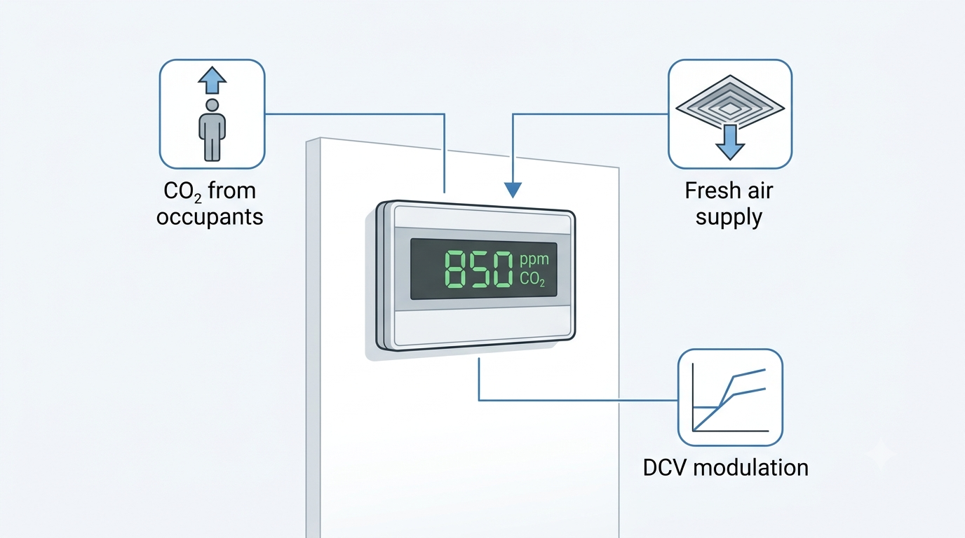
Ventilation systems sized for peak occupancy deliver far more outdoor air than necessary during periods of low or variable occupancy. A conference room designed for 40 people receiving full design airflow when only four people are present wastes substantial energy — the HVAC system overconditions outdoor air for no occupant benefit. Demand-controlled ventilation (DCV) addresses this by using CO₂ concentration as a proxy for occupancy, increasing outdoor air supply when CO₂ rises above a setpoint and reducing it when the space empties. CO₂ sensors are the measurement backbone of any DCV system. This guide covers sensor technology, placement strategies, calibration, output options, and selection criteria relevant to Australian commercial HVAC practice.
DCV is recognised in AS 1668.2 (the Australian Standard for mechanical ventilation in buildings) and is supported under the National Construction Code (NCC) as a strategy for achieving required minimum outdoor air rates while reducing energy consumption during variable occupancy. In practice, correctly commissioned DCV systems consistently deliver measurable reductions in both fan energy and conditioning load — provided the CO₂ sensors are correctly selected, placed, and maintained.
Why CO₂ as a Ventilation Indicator?
CO₂ is produced by human respiration at a rate of approximately 0.3 L/min per person at rest, rising with physical activity. Outdoor air contains approximately 420 ppm CO₂ as of the current 2024 baseline — elevated slightly from the 400 ppm figure used in older references. As occupancy increases in an enclosed space, CO₂ concentration rises above that ambient baseline. The rate of rise depends on the number of occupants, their metabolic rate, the volume of the space, and the outdoor air supply rate.
ASHRAE 62.1-2022 acknowledges CO₂ monitoring as a method for demand-controlled ventilation. A setpoint of 1,000 ppm is widely used as the upper threshold — representing the approximate equilibrium CO₂ level when ventilation is provided at the ASHRAE 62.1 person-based rate for typical office occupancy. The differential between the 420 ppm outdoor baseline and the 1,000 ppm upper setpoint provides approximately 580 ppm of working range for proportional control. An important qualification: CO₂ is an indicator of occupancy and metabolic load, not a direct measure of all indoor air quality parameters. It does not indicate elevated VOC, formaldehyde, particulate matter, or humidity. DCV based on CO₂ is appropriate for spaces where occupant-generated CO₂ is the primary driver of ventilation need — offices, conference rooms, classrooms, auditoriums, and gymnasiums. It is not appropriate as a standalone ventilation control strategy in kitchens, laboratories, car parks, or spaces with significant non-occupant-related pollutant sources.
NDIR Sensing Technology
Non-Dispersive Infrared (NDIR) is the standard CO₂ sensing technology in all HVAC-grade sensors. Alternative technologies — including electrochemical cells and metal oxide semiconductor (MOS) sensors — are occasionally found in low-cost consumer devices but are not appropriate for commercial HVAC DCV applications due to poor long-term stability, cross-sensitivity to other gases, and limited service life.
The NDIR operating principle involves four components:
- An infrared light source emits a broadband IR signal through a sealed sample chamber through which the measured air continuously flows.
- CO₂ molecules absorb IR radiation at a specific wavelength of 4.26 μm. The greater the CO₂ concentration, the greater the IR absorption at that wavelength.
- A reference wavelength — one not absorbed by CO₂ — is measured simultaneously via a second detector channel. The ratio of absorbed to reference signal is converted to a CO₂ concentration reading in ppm, compensating for any gradual degradation of the IR source.
- Signal conditioning circuitry applies temperature compensation and outputs a calibrated reading via the sensor's analogue or digital output.
NDIR has three significant advantages for HVAC applications: accuracy of ±50 ppm at calibration is readily achievable; the NDIR optical cell has no chemical reaction and does not deplete over time, giving service lives of 10–15 years; and the technology is stable across the humidity and temperature ranges encountered in occupied building environments.
Automatic Baseline Calibration (ABC)
Most HVAC CO₂ sensors use Automatic Baseline Calibration (ABC), sometimes labelled as self-calibration or background calibration. The ABC algorithm assumes that at some point during a regular cycle — typically 7–14 days — the monitored space will be unoccupied and the sensor will be exposed to outdoor air at near-ambient CO₂ concentration. Over each cycle, the algorithm records the minimum CO₂ reading and, after several cycles, uses a statistical average of those minima to reset the sensor's zero baseline.
ABC is effective and low-maintenance for the overwhelming majority of commercial HVAC applications — offices, schools, retail, conference facilities — where spaces are reliably unoccupied overnight and on weekends. The algorithm typically maintains calibration within ±50 ppm across the sensor's service life in these conditions.
ABC fails in continuously occupied spaces such as certain hospital wards, 24-hour call centres, some manufacturing and data centre environments, and other facilities that are never genuinely unoccupied. In these applications, commission sensors with manual calibration capability and calibrate against a known reference gas — 400 ppm reference gas in nitrogen is the standard for zero calibration. Alternatively, relocate the sensor to an adjacent space that is genuinely unoccupied overnight for its calibration cycle. Schedule annual manual verification in any application where there is uncertainty about whether the space achieves full unoccupied periods.
Sensor Placement — Wall (Zone) vs. Duct Return
Two primary mounting strategies are used in DCV systems, each with distinct advantages depending on the system architecture.
Wall (zone) sensors are mounted in the occupied space at breathing height — 1.2–1.5 m above finished floor level. They directly measure the CO₂ concentration in the zone being controlled, providing the highest accuracy for individual zone DCV. Wall sensors are best practice for single VAV box control, individual room DCV, and any application where occupancy varies substantially between adjacent zones. Multiple zone sensors are required in multi-zone systems — one per independently controlled zone. Common placement errors to avoid: proximity to supply air diffusers (dilution effect will cause the sensor to underread), proximity to operable windows or doors (infiltration from corridors or outdoors will depress the reading), and proximity to return air grilles (elevated local CO₂ adjacent to the grille is not representative of the zone average).
Duct return sensors are mounted in the return air duct serving the air handling unit (AHU), or in the AHU return air section itself. They measure a blended CO₂ concentration representing all zones returning air to that AHU. A single duct sensor per AHU replaces the need for individual zone sensors and can be used to control the AHU's outdoor air damper directly. The trade-off is accuracy: the mixed-air reading averages occupancy across all zones, so a high-occupancy conference room returning air to the same AHU as an empty office will have its occupancy signal diluted. Duct return sensors are most appropriate for large open-plan areas with relatively uniform occupancy distribution — not for buildings with a mix of high and low occupancy rooms on the same AHU.
| Placement Option | Best Use Case | Measurement Accuracy | Installation Complexity |
|---|---|---|---|
| Wall (zone) sensor | Single zone or individual room control | Highest — direct zone measurement | Higher (one sensor per controlled zone) |
| Duct return sensor | Central AHU serving uniform occupancy | Lower — averaged mixed-air reading | Lower (one sensor per AHU) |
| Zone + duct combination | Large buildings with mixed space types | Comprehensive | Highest cost and complexity |
DCV Setpoints and Control Logic
A proportional DCV control strategy using CO₂ as the process variable is straightforward to implement in any BMS capable of reading an analogue input. The following setpoints are typical for Australian commercial office applications under AS 1668.2 design criteria:
- Below 700 ppm: Maintain minimum outdoor air rate — typically 10 L/s per person (or the area-based minimum) per AS 1668.2 for office occupancy. The outdoor air damper holds at the minimum position.
- 700–1,000 ppm: Modulate the outdoor air damper proportionally from minimum to design (maximum) outdoor air rate as CO₂ rises through this range.
- Above 1,000 ppm: Hold outdoor air damper at maximum outdoor air rate. Investigate if CO₂ remains elevated for extended periods despite maximum ventilation — this may indicate sensor fault, unusual occupancy, or inadequate design outdoor air rate.
- Above 1,500 ppm (alarm): Generate a BMS alarm for operator investigation. Sustained readings above 1,500 ppm in a well-ventilated commercial space indicate either sensor malfunction, blocked outdoor air intake, or occupancy significantly exceeding the design assumption.
The CO₂ sensor output — typically 4-20 mA or 0-10 V scaled to 0–2,000 ppm — is wired to a BMS analogue input. The BMS modulates the outdoor air damper actuator using a PID control loop with CO₂ concentration as the process variable and outdoor air damper position as the control output. Wind-up protection and minimum position overrides are important configuration considerations: the outdoor air damper must never close below the hygienic minimum regardless of CO₂ level, and the control loop must be tuned to the relatively slow time constant of zone CO₂ response (typically 5–20 minutes for a well-mixed office zone).
The energy benefit of DCV is most pronounced in spaces with highly variable occupancy. Conference rooms, auditoriums, lecture theatres, and gymnasium spaces are frequently designed for peak occupancy loads that are achieved only a fraction of the time. DCV in these spaces can reduce HVAC energy consumption by 15–30% compared to constant-volume outdoor air systems, with the majority of savings occurring in the conditioning energy required to treat outdoor air (cooling, dehumidification, or heating depending on climate and season).
Output Signal and BMS Integration
CO₂ sensor output type must match the BMS or controller input available at the installation. Three output formats are in common use in Australian commercial BAS practice:
- 4-20 mA analogue: Scaled to 0–2,000 ppm or 0–5,000 ppm. The 4 mA lower-range value allows the BMS to detect an open-circuit fault (a 0 mA signal indicates wiring failure, not zero CO₂). Preferred for longer cable runs where voltage drop would affect a 0-10 V signal. Maximum practical run length with 4-20 mA is typically 300 m with standard 0.75 mm² cable.
- 0-10 V analogue: Scaled to the same ppm ranges. Simpler wiring (two-conductor, no loop current to maintain), but susceptible to voltage drop on long runs and to noise pickup in electrically noisy environments. Suitable for runs up to approximately 30–50 m in well-screened cable.
- BACnet MS/TP: Digital RS-485 communication. CO₂ concentration is presented as a BACnet Analogue Input object with engineering units (ppm), valid range, and fault status accessible as standard BACnet properties. Preferred where the BMS has available MS/TP field bus capacity, as it eliminates analogue input wiring, provides richer diagnostic data, and supports combination sensors delivering multiple parameters over a single two-wire connection. See our guide on BACnet vs Modbus (anticipated — verify URL before publishing) for protocol selection guidance.
- Modbus RTU: Common in sensors that also measure temperature and humidity, enabling all three measurements to be transmitted over a single screened twisted-pair bus.
Sensor Accuracy and Drift
Specifying CO₂ sensor accuracy correctly requires understanding both the initial calibration accuracy and the long-term drift behaviour. Typical HVAC-grade NDIR CO₂ sensor specifications are:
| Parameter | Typical Specification |
|---|---|
| Measurement range | 0–2,000 ppm (HVAC DCV) or 0–5,000 ppm (industrial / safety monitoring) |
| Accuracy at calibration | ±50 ppm ± 3% of reading (e.g., ±80 ppm at 1,000 ppm reading) |
| Long-term drift (with ABC) | <20 ppm per year, corrected by ABC algorithm |
| Temperature compensation range | 0–50°C (automatic); some models to 60°C for duct applications |
| Operating humidity | 0–95% RH, non-condensing |
| Rated service life | 10–15 years (NDIR optical cell) |
Temperature compensation is particularly important for duct-mount sensors, where the air temperature may differ substantially from the ambient room temperature, and where rapid airflow can affect the thermal equilibrium of the sensor cell. Verify that the sensor's stated temperature compensation range covers the expected duct temperature at the installation point — in mixed-air duct sections in Australian climates, temperatures between 10°C and 40°C are common depending on season and system configuration.
CO₂ Sensors from BAPI — Available Through Controls Traders
BAPI (Building Automation Products Inc.) offers a comprehensive range of wall-mount and duct-mount CO₂ sensors for HVAC DCV applications, available in Australia through Controls Traders. The BAPI CO₂ sensor range includes standalone CO₂ units for straightforward DCV applications as well as combination sensors integrating CO₂ with relative humidity and temperature measurement in a single housing — an arrangement that reduces wiring and installation time significantly where all three parameters are required in a zone.
BAPI CO₂ sensors support multiple output options including 4-20 mA, 0-10 V, BACnet MS/TP, and Modbus RTU, making them compatible with all major BMS platforms used in Australian commercial and industrial buildings. Combination sensors with digital outputs are particularly efficient in multi-zone systems, where a single RS-485 bus can carry CO₂, humidity, and temperature data from multiple sensors to the BMS without the wiring overhead of individual analogue inputs per parameter. For sensor selection, product availability, and technical assistance, contact the Controls Traders team.
Frequently Asked Questions
What CO₂ setpoint should I use for demand-controlled ventilation?
1,000 ppm is the widely used upper setpoint, based on ASHRAE 62.1 guidance and representing approximately the equilibrium CO₂ level when ventilation is provided at the standard person-based rate for office occupancy. A proportional control band of 700–1,000 ppm is common, where the outdoor air damper modulates from minimum to maximum outdoor air as CO₂ rises through this range. Some projects specify tighter setpoints — 800–850 ppm upper limit — where higher indoor air quality targets are required. Confirm the setpoint strategy with the project mechanical specification and the relevant authority in your jurisdiction, as NCC DtS provisions and Green Star or NABERS credits may impose specific requirements.
Do CO₂ sensors need to be calibrated regularly?
Sensors with Automatic Baseline Calibration (ABC) self-calibrate by periodically resetting their zero to the minimum reading over a 7–14 day cycle, assuming the space is unoccupied during that period. In genuinely variable-occupancy spaces, ABC typically maintains calibration within ±50 ppm over multiple years without manual intervention. For spaces that are never fully unoccupied, schedule annual manual calibration using 400 ppm reference gas. Sensors that are consistently reading more than 100 ppm above a calibrated reference despite ABC correction, or that have exceeded the manufacturer's stated service life of 10–15 years, should be replaced rather than recalibrated.
Should I mount CO₂ sensors on the wall or in the return duct?
Wall-mount (zone) sensors in the occupied space provide the most accurate reading for individual zone DCV — they measure actual occupant CO₂ without the averaging effect of mixing with air from adjacent zones. Duct-return sensors are suitable for central AHUs serving large, relatively uniform occupancy spaces, where a mixed-air reading is an acceptable proxy for zone-level CO₂ concentration. For conference rooms, classrooms, and other variable-occupancy rooms, wall-mount sensors in each room give significantly better control performance and are recommended where budget permits. A duct return sensor can still be used as a secondary check or system-level override in combination with zone sensors.
Can CO₂ sensors detect gases other than CO₂?
NDIR CO₂ sensors are designed specifically to measure CO₂ concentration by targeting the 4.26 μm absorption wavelength; they do not measure VOCs, formaldehyde, particulate matter, carbon monoxide, or other indoor air quality parameters. For spaces where multiple pollutant sources exist — commercial kitchens, laboratories, print rooms, car parks — DCV based on CO₂ alone is insufficient to ensure adequate ventilation for all contaminants. In those applications, CO₂ monitoring may still be included as part of a broader IAQ strategy, but ventilation rates must not be reduced below the level required to dilute non-occupant-generated pollutants to safe concentrations.
What is the typical service life of an NDIR CO₂ sensor?
NDIR CO₂ sensors typically carry a rated service life of 10–15 years. Unlike electrochemical sensors, which rely on a chemical reaction that gradually depletes a reagent, the NDIR optical cell operates without a consumable element — degradation occurs slowly through contamination of the optical surfaces and gradual ageing of the infrared source. Sensors that are consistently reading more than 100 ppm above a calibrated reference after ABC correction, or that have exceeded the manufacturer's stated service life, should be scheduled for replacement as part of building maintenance planning. Record sensor installation dates in the BMS or asset register to facilitate planned replacement programmes.

Siemens SSA, SKB, SAY and SAS Actuator Series: A Technical Guide
.png)
Siemens actuators are among the most commonly specified in Australian commercial HVAC and building automation systems. The SSA, SAS, SAY, and SKB series cover the dominant damper and valve control applications — from compact VAV box dampers through to large AHU mixing boxes and modulating chilled water coil valves. Each series has a defined application domain; selecting the correct series avoids field rework and ensures the actuator meets the mechanical and control requirements of the application. Specifying a damper actuator with insufficient torque, or a linear valve actuator where a rotary actuator is needed, will result in either field failure or a costly replacement during commissioning.
This guide covers the technical characteristics of each series, the model number decoding logic for the HVAC actuator range, actuator sizing methodology, and the key selection criteria for Australian commercial projects. Fail-safe behaviour — which series and variants offer spring return, and in which direction — is addressed specifically, as this is a common source of specification errors and non-compliance with damper actuator requirements under AS 1668 and the National Construction Code.
Series Overview
| Series | Application | Motion | Spring Return | Typical Torque / Force | Key Applications |
|---|---|---|---|---|---|
| SSA | Dampers | Rotary | Yes | 3–45 Nm | Outdoor air dampers, exhaust dampers, AHU mixing boxes, economiser dampers, relief dampers |
| SAS | Dampers | Rotary | Yes | 2.5–10 Nm | VAV terminal unit dampers, small HVAC zone dampers |
| SAY | Valves (globe) | Linear (push-pull) | Yes | 300–800 N | 2-way and 3-way globe valves on AHU cooling and heating coils |
| SKB | Valves (ball/butterfly) | Rotary (quarter-turn) | Optional | 10–150 Nm | Ball valves, butterfly valves, isolation and modulating applications on larger pipe sizes |
All series are available through Controls Traders as an authorised Siemens distributor for South Australia and nationally.
SSA Series — Spring-Return Damper Actuators
The SSA series is Siemens' primary line of spring-return rotary actuators for air-side damper applications. Spring return is the defining attribute of the series: the electric motor drives the actuator toward its operating position while simultaneously compressing a mechanical spring. On loss of power or control signal, the spring drives the actuator to a defined fail-safe position without requiring any external power or control input. This behaviour is a code requirement for outdoor air dampers under AS 1668.2 (to close and isolate the air stream in cold climates, preventing freeze damage to heating coils) and for any damper serving a life safety function under AS 1668.1.
The SSA range spans the torque requirements of most commercial HVAC damper installations. Key torque classes within the range include:
- SSA31 — 3 Nm: suited to small VAV box dampers and compact duct-mounted dampers up to approximately 0.3 m² area with standard blade seals.
- SSA61 — 10 Nm: the most widely used SSA variant in Australian commercial projects. Appropriate for medium commercial dampers of approximately 0.6–0.8 m² with standard parallel or opposed blades and moderate sealing requirements.
- SSA81 — 25 Nm: for larger AHU mixing box dampers and economiser dampers where damper area, blade count, or tight low-leakage seals require higher torque.
- SSA161 — 45 Nm: the highest-torque variant in the standard SSA range, suitable for large relief and exhaust dampers on major air handling plant.
Control signal variants are identified in the model number by a two-digit decimal suffix:
- .03 — on/off (two-position), 24 V AC/DC. The actuator drives fully to the open position when energised and spring-returns to fail-safe when de-energised. Used for simple two-position control (open/closed) without intermediate positioning.
- .53 — three-point floating. The BMS sends open and close pulse commands; the actuator drives in the commanded direction for the duration of the pulse. Used with floating output controllers or thermostats that do not have an analogue output.
- .73 — 0–10 V proportional modulating. A continuous analogue input signal positions the actuator proportionally across its 0–95° rotation. This is the standard variant for BMS analogue output control.
Fail-safe position must be specified separately from the torque class and control variant. SSA actuators are available as normally-closed (NC — spring drives the actuator to the closed position on power loss, standard for outdoor air dampers and mixed-air dampers) or normally-open (NO — spring drives the actuator to the fully open position, used for relief dampers and exhaust dampers where opening on power loss prevents over-pressurisation). Confirm the required fail-safe direction with the mechanical engineer or BAS contractor before ordering.
Many SSA models support integral or field-fitted auxiliary switches — end-of-travel feedback contacts that close when the damper reaches the fully open or fully closed position. These dry contact outputs provide a binary position proof signal to the BMS, which is essential in fire/smoke control sequences where the BMS logic must confirm damper position before permitting a fan to start. The presence and configuration of auxiliary switches is identified in the suffix codes of the full model number.
SAS Series — Compact Spring-Return Actuators
The SAS series serves small dampers and VAV terminal unit applications where the physical dimensions of the SSA actuator exceed the available mounting space in the unit. The torque range of 2.5–10 Nm covers single-blade and small multi-blade dampers typically found inside VAV boxes and small duct-mounted zone dampers. The mounting arrangement — shaft clamp geometry, bracket profile, and overall actuator footprint — is designed to fit the smaller damper shafts and mounting configurations found in manufactured VAV terminal units from major HVAC manufacturers.
Control variants in the SAS series parallel those in the SSA: on/off, three-point floating, and 0–10 V modulating variants are available, with spring return as standard. The selection between SSA and SAS for a given application is primarily determined by physical fit — damper shaft diameter, available mounting depth, and the space envelope inside the terminal unit or duct section — rather than by control or torque characteristics alone.
SAY Series — Linear Spring-Return Valve Actuators
The SAY series drives valve stems in a linear (push-pull) motion, making it the correct actuator type for globe valves with a rising stem. Globe valves are the predominant valve type on AHU chilled water and hot water coils in Australian commercial HVAC systems, as their flow characteristic (typically equal-percentage) is well-matched to coil heat transfer behaviour. Spring return in the SAY provides fail-safe valve positioning — fail-closed is standard for heating and cooling coil valves, ensuring that the coil valve closes on power loss and prevents uncontrolled heating or cooling of the conditioned space.
Key technical specifications for the SAY series:
- Stroke: 5.5 mm standard. This is directly compatible with the Siemens VVI, VVF, and VXF globe valve body series, which are designed around the same stroke.
- SAY31 — 300 N force: suitable for DN15 to DN32 globe valves on secondary chilled water and heating water circuits at standard HVAC differential pressures. This is the most commonly selected SAY variant for AHU coil valve applications.
- SAY61 — 800 N force: required for valves on primary circuits with higher differential pressure, larger DN valve bodies, or where system pressure fluctuations require a higher close-off force margin.
- Control input: 0–10 V modulating is standard. Versions accepting 4–20 mA input are available for applications where the BMS analogue output is current-based.
- Mounting: integral bracket provides direct coupling to the Siemens VVx valve series. Adapter kits are available for mounting to compatible third-party valve bodies — stem travel compatibility with the 5.5 mm stroke must be confirmed before specifying an adapter.
Close-off pressure verification is a critical step in SAY selection. The actuator closing force must exceed the hydraulic force acting on the valve disc at maximum system differential pressure. The required close-off force (N) can be estimated as: Kvs (m³/h) × system ΔP (kPa) × a valve-type factor. For most secondary HVAC circuits at standard ΔP, the SAY31 at 300 N provides adequate close-off force for DN15–32 globe valves. Verify against the valve manufacturer's published close-off force data for the specific valve and system pressure combination before finalising the selection.
SKB Series — Rotary Valve Actuators
The SKB series drives quarter-turn applications: ball valves and butterfly valves, which require a 90° rotation to move between fully open and fully closed positions. Unlike the SSA damper actuator — which is designed for continuous modulating positioning across a 95° rotation — the SKB's mechanical design is optimised for the torque profile of ball and butterfly valves, which require significantly higher breakaway torque at the start of the opening stroke than running torque during normal modulation.
Spring-return and non-spring-return variants are both available in the SKB range. Spring-return SKB variants are selected for isolation applications where the valve must reach a defined fail-safe position — typically fail-closed for shutoff applications on condenser water or chilled water pipework. Non-spring-return (hold last position) variants are appropriate for modulating applications where the BMS can reliably reposition the valve after a power interruption, and where the fail-safe requirement is to remain in the last commanded position rather than drive to an end-of-travel position.
The torque range of 10–150 Nm in the SKB series covers ball valve and butterfly valve sizes from DN20 through to large-diameter butterfly valves on major plant. Torque selection requires matching the actuator's rated torque to the valve's required breakaway torque at maximum system differential pressure, with a minimum safety margin of 25% above the valve manufacturer's published breakaway torque figure. Breakaway torque for ball valves is typically 2–3 times the running torque; for butterfly valves it varies with disc geometry and seat type.
Decoding Siemens Actuator Model Numbers
Siemens uses a structured part number system for the HVAC actuator range. Reading the model number correctly is essential for confirming a specification and for identifying replacement parts in the field. The general structure is:
- First two characters — series identifier: SS = spring-return rotary (damper), SA = spring-return linear or non-spring-return linear/rotary (actuator), SK = rotary/ball valve actuator.
- Third character — application variant: A = rotary damper actuator (SSA/SAS), Y = linear valve actuator (SAY), B = rotary/ball valve actuator (SKB).
- Digits (e.g., 31, 61, 81, 161) — force or torque class: higher numbers indicate higher rated torque (Nm) or force (N). These do not directly correspond to the rated torque value — they are class designators. Refer to the Siemens HVAC product catalogue for the torque or force value associated with each class designator within each series.
- Decimal suffix (e.g., .03, .53, .73) — control input type: .03 = on/off two-position (24 V AC/DC), .53 = three-point floating (open/close pulse), .73 = 0–10 V modulating proportional input.
- Trailing letter codes — options: S = integral auxiliary switch (end-of-travel feedback), U = universal voltage (accepts 24–240 V AC/DC on a single model), A1 = 4–20 mA input variant.
Two practical examples illustrate the decoding:
- SSA61.73: Spring-return, rotary, damper actuator (SSA series), 10 Nm torque class (61), 0–10 V modulating proportional input (.73). No auxiliary switch, standard 24 V AC/DC supply.
- SAY31.53: Spring-return, linear, valve actuator (SAY series), 300 N force class (31), three-point floating control input (.53). Suitable for AHU coil globe valves controlled from a floating output thermostat or BMS.
For engineers and technicians familiar with Belimo actuator model numbers, the naming philosophy differs — Belimo encodes product family, torque, and options differently — but the underlying approach of reading torque class, signal type, and spring-return status from the part number is similar. The Controls Traders article on Belimo model numbers explained covers the Belimo decoding methodology for comparison.
Actuator Sizing Guide
Correct actuator sizing prevents both field failure (undersized actuator cannot overcome damper or valve resistance) and unnecessary cost (oversized actuator is larger and more expensive than required). A systematic approach reduces the likelihood of specification errors.
Damper actuators (SSA and SAS series):
Required torque (Nm) = Damper area (m²) × Specific torque (Nm/m²)
Typical specific torque values by damper type:
- Parallel-blade dampers, standard seals: 8–12 Nm/m²
- Opposed-blade dampers, standard seals: 10–16 Nm/m²
- Dampers with tight low-leakage blade seals (Class 1 or Class 2 leakage to AS 4117): 15–20 Nm/m²
Apply a minimum 25% safety margin to the calculated torque to account for manufacturing tolerances, seal ageing, and blade linkage wear over the actuator's service life. Where the damper manufacturer publishes a required actuator torque specification, use that value — with the 25% margin applied — in preference to the area-based calculation. Select the next standard SSA or SAS torque class above the calculated requirement.
Linear valve actuators (SAY series):
Required force (N) must equal or exceed the valve's close-off force at maximum system differential pressure. This is published in the valve datasheet as a "required actuator force at rated ΔP" figure for Siemens VVI/VVF/VXF valves. The SAY31 at 300 N covers the majority of AHU coil valve applications on secondary HVAC circuits at standard design differential pressures. Where the calculation indicates a required force approaching the SAY31 rating, specify the SAY61 (800 N) to maintain an adequate margin at maximum system pressure transient conditions.
Rotary valve actuators (SKB series):
Required torque (Nm) ≥ valve breakaway torque at maximum system ΔP × 1.25 safety margin. Ball valve breakaway torque is typically 2–3 times running torque; the exact figure is published in the valve manufacturer's data. Butterfly valve breakaway torque varies with disc geometry, seat material, and the direction of flow relative to disc position — consult the valve datasheet.
For complex selections — particularly where system ΔP varies significantly across operating conditions, or where the damper or valve manufacturer's data is not available — contact Controls Traders for selection support. The Siemens HVAC product catalogue (Catalogue S) provides the full torque and force data for each model in the SSA, SAS, SAY, and SKB series.
Controls Traders stocks the Siemens HVAC actuator range across the SSA, SAS, SAY, and SKB series for Australian commercial projects. For selection assistance, lead time confirmation, or to discuss actuator requirements for a specific project, contact the Controls Traders team.
Frequently Asked Questions
What is the difference between the SSA and SAS series?
Both are spring-return rotary damper actuators for air-side HVAC applications. The SSA covers a wider torque range (3–45 Nm) and offers more control signal variants and auxiliary switch configurations, making it the standard selection for medium and large commercial dampers from approximately 0.3 m² upward. The SAS is more compact in its physical form factor, intended specifically for smaller dampers and VAV terminal unit applications where the SSA's body dimensions do not fit within the available mounting envelope inside the unit or duct section. The selection is primarily determined by physical fit rather than control requirements.
How do I choose between spring-return (SSA) and non-spring-return (SKB non-spring) actuators?
Use spring-return whenever the damper or valve must reach a defined fail-safe position — open or closed — on loss of power or control signal. This is mandatory for outdoor air dampers under AS 1668.2 (fail-closed to isolate the air stream and protect heating coils in cold climates), for fire and smoke dampers under AS 1668.1, and for any isolation valve where fail-safe closure is a safety or process requirement. Use non-spring-return (hold last position) where the fail-safe requirement is to maintain the last commanded position, or where the BMS can reliably reposition the actuator within an acceptable time after power restoration — typically modulating valves on secondary circuits in systems with reliable power supply.
Can SAY actuators be fitted to non-Siemens valve bodies?
Yes. Siemens and third-party suppliers provide adapter kits to mount the SAY series to compatible globe valve stems. Before specifying an adapter, verify two critical parameters: first, that the valve stem travel is compatible with the SAY's 5.5 mm stroke — some globe valves use a different stroke and require a stem nut adjustment or a different actuator entirely; second, that the SAY's force rating (300 N for SAY31, 800 N for SAY61) meets the valve's published close-off force requirement at the maximum system differential pressure. Where neither of these can be confirmed from the valve manufacturer's data, contact Controls Traders for guidance.
How do I decode a Siemens actuator model number?
The first two letters identify the series: SS for spring-return rotary damper actuators, SA for linear or non-spring rotary actuators, SK for rotary ball or butterfly valve actuators. The following letter identifies the application variant: A for rotary damper, Y for linear valve, B for rotary ball valve. The digits (31, 61, 81, 161) identify the torque or force class — higher numbers indicate higher rated values. The decimal suffix identifies the control input: .03 is on/off two-position, .53 is three-point floating, .73 is 0–10 V modulating. Trailing letters indicate options: S for integral auxiliary switch, U for universal voltage (24–240 V AC/DC). The full decoding table is published in Siemens Catalogue S — HVAC Products.
How much torque do I need for a 1.2 m² damper?
Using a specific torque of 12 Nm/m² for a parallel-blade damper with standard seals: 1.2 m² × 12 Nm/m² = 14.4 Nm. Applying a 25% safety margin: 14.4 × 1.25 = 18 Nm. The next standard SSA class above 18 Nm is the SSA81 at 25 Nm, which is the correct selection for this damper. For a damper fitted with tight low-leakage blade seals (Class 1 or Class 2 leakage rating), increase the specific torque assumption to 16–20 Nm/m² and recalculate — in this case the SSA81 at 25 Nm remains the appropriate selection but with a reduced safety margin, and the SSA161 at 45 Nm may be warranted if the damper manufacturer's published torque specification exceeds 25 Nm.

Differential Pressure Sensors for HVAC: A Technical Selection Guide
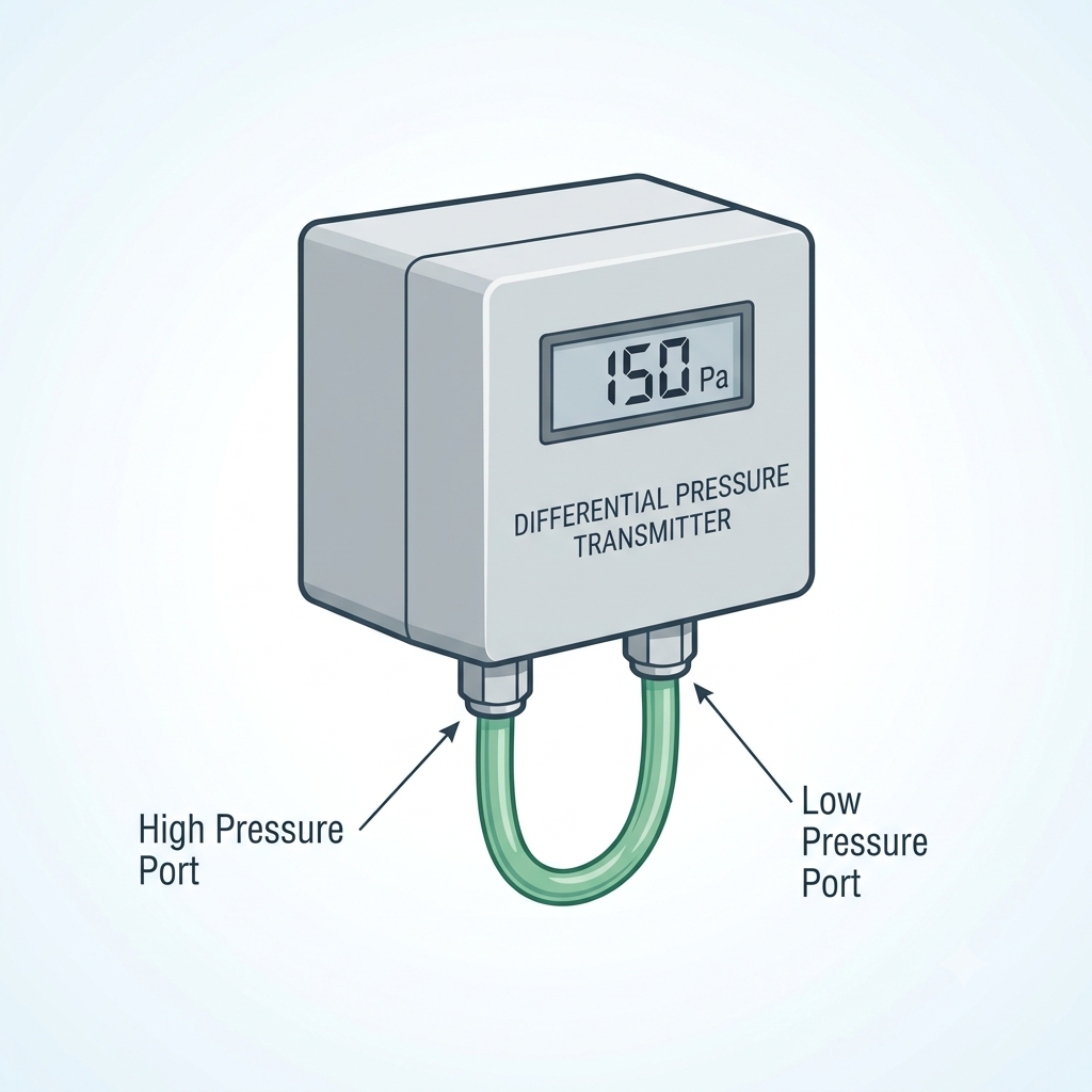
Differential pressure (DP) measurement is fundamental to HVAC system operation. Whenever air or fluid passes through a restriction — a filter bank, a coil, a duct fan — there is a pressure difference across it. Differential pressure sensors measure that difference and convert it to a signal a BMS or controller can act on. The sensor class covers an enormous range of applications: from detecting a 5 Pa pressure differential across a door gap in a hospital isolation room, to monitoring the 1,000+ Pa pressure rise across a supply air fan. Selecting the wrong sensor — one with a range that is too wide, or an output that does not match the BMS analogue input — results in poor measurement resolution, unnecessary field rework, or incorrect alarm set points.
This guide covers the operating principles behind DP sensors, the pressure ranges and output signal types available, and a step-by-step selection process applicable to the most common HVAC applications. It references products available through Controls Traders, including the BAPI differential pressure sensor range, which covers room pressurisation through to high-pressure industrial air handling. For a broader overview of HVAC sensors available from Controls Traders, including temperature, humidity, and CO₂ types, visit the sensors category page.
How Differential Pressure Sensors Work
A differential pressure sensor has two pressure ports — a high-pressure port and a low-pressure port — each connected to the measurement point via tubing or direct-mount fittings. The sensor measures the pressure at each port and outputs a signal proportional to the difference between them. When both ports are at equal pressure (the reference condition), the output represents zero differential pressure. When the high-pressure port is at greater pressure than the low-pressure port, the output increases proportionally.
Three primary sensing element technologies are used in HVAC-grade DP sensors:
- Piezoresistive silicon diaphragm — the most common technology in HVAC differential pressure sensing. Differential pressure deflects a silicon diaphragm; the resulting strain changes the resistance of doped silicon elements arranged in a Wheatstone bridge circuit. The bridge imbalance is amplified and conditioned to produce the output signal. This technology is robust, accurate to ±2% of full scale in HVAC-grade instruments, and well-suited to both air and water applications.
- Capacitive sensing — differential pressure deflects a diaphragm, changing the capacitance between two plates on either side of it. Capacitive sensors offer excellent resolution and are preferred for ultra-low pressure ranges below 25 Pa, where the diaphragm deflection is very small and a capacitance measurement is more sensitive than a resistance measurement. This technology is the standard choice for hospital room pressurisation applications.
- Variable reluctance — a mechanical diaphragm changes the reluctance of a magnetic circuit. Less common in modern HVAC applications, this technology appears in some legacy and industrial transmitters. It is more robust against overrange events but is rarely specified in new HVAC installations.
Signal conditioning electronics convert the raw sensor element output to a standard electrical signal — 4–20 mA, 0–10 V, or a digital protocol such as BACnet MS/TP or Modbus RTU. Accuracy of ±2% of full scale is typical for standard HVAC-grade instruments; high-accuracy process transmitters achieve ±0.25% of full scale but are rarely required in building HVAC applications.
Pressure Ranges and HVAC Applications
The pressure range of a DP sensor determines both its measurement ceiling and its resolution. A sensor with a 0–6,250 Pa range used on a 25 Pa room pressurisation application will produce only 0.4% of its full output at the target set point — effectively unusable for control. Matching the sensor range to the application is critical.
| Range Category | Pressure Range (Pa) | Typical HVAC Application |
|---|---|---|
| Ultra-low | <25 Pa | Hospital isolation room pressurisation, clean room pressure monitoring |
| Low | 25–125 Pa | Filter monitoring in low-velocity systems, pharmaceutical clean room pressure |
| Medium | 125–1,250 Pa | VAV box airflow measurement, supply duct static pressure, AHU filter banks, fan monitoring |
| High | 1,250–6,250 Pa | High-velocity ducted systems, industrial air handling units |
| Bidirectional | ±12.5 to ±250 Pa | Room pressurisation where differential direction may reverse |
The bidirectional range category deserves specific attention for room pressurisation applications. A unidirectional sensor (0 to +X Pa) can only report pressure in one direction. If the controlled space momentarily goes negative relative to the reference — which can occur during door opening, a supply fan trip, or poor initial commissioning — a unidirectional sensor will either read zero or saturate at its lower limit. It cannot communicate to the building automation system that the pressure has reversed. A bidirectional sensor (±X Pa) produces an output above mid-scale for positive pressure and below mid-scale for negative pressure, allowing the BMS to detect and respond to pressure reversals.
Key HVAC Applications
Filter Monitoring
Filter monitoring is the most common DP sensor application in commercial HVAC. A sensor is installed across the filter bank — high-pressure port upstream, low-pressure port downstream — and the output is monitored by the BMS. As filters accumulate dust and particulate, the pressure drop across the bank increases from the clean filter resistance toward the final resistance at which the filter should be changed.
ASHRAE recommends DP-based filter monitoring rather than time-based scheduling because identical filters in different systems — one handling clean office air, another handling dusty warehouse return air — will reach their final resistance at very different rates. Time-based replacement wastes filters that still have useful life, or leaves loaded filters in service beyond their design change point.
For MERV 8–13 filters at typical AHU face velocities of 2–3 m/s, initial resistance ranges from 40–80 Pa and final resistance (the filter change alarm point) is typically 150–250 Pa. Select a sensor with a range approximately 20% above the expected final resistance. A 0–250 Pa sensor is appropriate for many commercial HVAC filter banks; a 0–500 Pa sensor provides additional headroom for higher face velocity applications.
VAV Box Airflow Measurement
VAV box airflow measurement uses a DP sensor paired with a Pitot tube, flow cross, or factory-fitted flow station inside the VAV terminal unit. The flow element creates a measurable velocity pressure differential by separating total pressure (measured at the upstream stagnation point) from static pressure. The VAV controller derives volumetric airflow using the Bernoulli relationship: V = √(2ΔP/ρ), where V is velocity (m/s), ΔP is velocity pressure (Pa), and ρ is air density (approximately 1.2 kg/m³ at standard conditions). Volumetric flow is then calculated by multiplying velocity by the known duct cross-section area.
Typical velocity pressure at an airflow of 5 m/s in a 300 mm round duct is approximately 15 Pa. At minimum design airflow — often 30–40% of maximum — velocity pressure drops to approximately 1.5–2.5 Pa, placing demanding resolution requirements on the sensor. Select a sensor with a range of 0–125 Pa to cover the full VAV operating range, and confirm that the sensor's resolution is adequate at the minimum flow condition.
Building Pressurisation
Building pressurisation control is a critical function in hospitals, clean rooms, pharmaceutical laboratories, and isolation rooms. Controlled pressure differentials prevent cross-contamination between spaces: positive pressure rooms (+12.5 Pa relative to adjacent corridor) push air outward, preventing particulates from entering; negative pressure rooms (−12.5 Pa) draw air inward, preventing airborne contaminants from escaping. These requirements are governed by AS 1668 and the National Construction Code (NCC/BCA) for healthcare facilities.
Sensors for this application must be bidirectional with adequate resolution at the set point. A ±25 Pa bidirectional sensor is appropriate for a ±12.5 Pa target. Resolution of 0.1 Pa or better is required to support tight pressure control within ±1–2 Pa of set point. Mount the sensor in a location with stable temperature — avoid direct exposure to supply air diffusers or locations subject to temperature swings that cause zero drift. Reference the low-pressure port to a location representative of corridor or adjacent space pressure, not immediately adjacent to a supply diffuser or door gap.
Fan and AHU Performance Monitoring
AHU performance monitoring uses DP measurement across the complete air handling unit — from inlet plenum to supply fan outlet — or across individual components such as cooling coils and heating coils. The DP baseline is established at commissioning and stored in the BMS. Deviation from the baseline indicates component fouling: a rising DP across a cooling coil indicates biofilm or scale accumulation; a rising DP across the complete AHU may indicate a combination of filter loading and coil fouling. DP-based AHU monitoring allows maintenance to be targeted to actual condition rather than calendar schedules.
Sensor vs. Transmitter — Terminology
The terms DP sensor and DP transmitter are used interchangeably throughout HVAC specifications and product catalogues. Technically, a sensor refers to the detecting element — the silicon diaphragm, capacitive cell, or mechanical element that responds to pressure. A transmitter includes signal conditioning circuitry and a standard electrical output that can be connected directly to a BMS analogue input. In HVAC practice, when a project specification calls for a "DP sensor, 0–250 Pa, 4–20 mA output," it is invariably referring to a complete transmitter. The technical distinction matters only when sourcing replacement detecting elements for an existing transmitter, or when specifying a field-mount transmitter to be connected to a remote sensing element.
Output Signal Options
Three output signal types are common in HVAC DP sensors:
- 4–20 mA (two-wire, loop-powered) — the most common output for HVAC BMS analogue inputs. A current-based signal is immune to voltage drop caused by cable resistance, making it suitable for long cable runs. The 4 mA live-zero is a significant reliability advantage: the BMS can distinguish between a zero-pressure reading (output at 4 mA) and a broken cable or failed sensor (output below 4 mA). Use 4–20 mA for cable runs exceeding 30 metres, or wherever signal cables share conduit with power wiring. Requires a 24 VDC supply at the BMS analogue input card.
- 0–10 V (three-wire) — simpler wiring at the sensor, with three conductors: supply positive, signal, and common. The 0 V zero is a disadvantage in fault detection — a broken wire reads the same as a zero-pressure reading. Susceptible to voltage drop on long cable runs; 4–20 mA is preferred for runs beyond 30 metres.
- Digital (BACnet MS/TP, Modbus RTU) — digital output sensors are increasingly common in modern HVAC installations. Advantages include multiple measured values in a single device (DP, temperature, and calculated volumetric flow), direct BMS integration without consuming analogue input cards, and engineering units embedded in the protocol. For guidance on BMS protocol selection, refer to the Controls Traders article on BACnet vs Modbus. Digital sensor commissioning requires bus address configuration and is more complex than analogue wiring, but the reduction in analogue input count can offset this effort on large projects.
Step-by-Step Selection Guide
- Determine required pressure range: calculate the maximum expected process pressure for the application (maximum filter final resistance, maximum fan static pressure, or maximum room pressurisation offset). Add a 20% margin, then round up to the nearest standard sensor range.
- Select output type: confirm the BMS analogue input type (4–20 mA or 0–10 V). Choose 4–20 mA for cable runs exceeding 30 metres or where the signal cable shares a conduit with power wiring. Choose 0–10 V for short runs where wiring simplicity is the priority.
- Choose mounting type: duct-mount (sensor body mounted directly in the duct wall, pressure ports penetrating the duct), remote-mount (sensor installed in an accessible location with polyethylene tubing running to the measurement points in the duct), or panel-mount (for MCC or control panel installation on pressurised duct systems).
- Specify process connections: barbed fittings for 6 mm polyethylene tubing are standard for most HVAC duct and air-side applications. NPT threaded ports are specified for higher-pressure water and steam applications where tubing compression fittings are appropriate.
- Confirm IP rating: IP54 is the minimum for duct-mounted sensors or sensors exposed to mechanical room conditions. IP65 or higher is required for sensors in wet areas or where water hosing is possible during cleaning.
- Check auto-zero feature: some sensors perform an automatic zero calibration at power-up, sampling the output with both pressure ports vented to atmosphere before entering normal operation. This is particularly valuable where the sensor is mounted near vibration sources — fans, pumps, compressors — that could induce zero drift over time.
BAPI Differential Pressure Sensors
BAPI (Building Automation Products Inc.) manufactures a comprehensive range of differential pressure sensors calibrated specifically for HVAC applications, available in Australia through Controls Traders' BAPI product range. BAPI sensors are designed for stable performance in the variable temperature and humidity conditions typical of mechanical rooms and duct interiors, where ambient conditions can fluctuate significantly over daily and seasonal cycles.
The BAPI DP sensor range covers ±12.5 Pa bidirectional sensors for hospital room pressurisation, through standard ranges of 0–125 Pa, 0–250 Pa, 0–500 Pa, 0–1,250 Pa, and 0–6,250 Pa for filter monitoring, VAV airflow, duct static pressure, and high-pressure industrial applications. Output options include 4–20 mA, 0–5 V, 0–10 V, and BACnet MS/TP digital output. The digital output models provide simultaneous DP and temperature measurements on the same device, reducing the analogue input count on BMS panels. BAPI sensors can be specified with field-adjustable ranges and zero suppression, allowing a single stocked model to serve multiple site pressure ranges.
For selection assistance — particularly for room pressurisation applications where sensor resolution and mounting location require careful consideration — contact Controls Traders. The Controls Traders technical team can confirm sensor selection against project specifications and advise on site-specific installation requirements.
Frequently Asked Questions
What pressure range do I need for filter monitoring?
For MERV 8–13 filters at typical AHU face velocities of 2–3 m/s, initial resistance is 40–80 Pa and final resistance (filter change point) is 150–250 Pa. Select a sensor rated 0–250 Pa or 0–500 Pa so the output does not saturate before the filter reaches its change point. Add a 20% range margin above the highest expected pressure to provide headroom for variations in face velocity and filter loading rate across different operating conditions.
Can a DP sensor measure airflow in a duct?
Yes, when paired with a Pitot tube, flow cross, or flow station that creates a measurable velocity pressure differential. The DP sensor measures the difference between total pressure (stagnation) and static pressure, which is equal to velocity pressure at that point. The VAV controller or BMS then applies V = √(2ΔP/ρ) and the duct cross-section area to calculate volumetric flow in m³/s or L/s. Sensor resolution at minimum flow conditions is the critical selection parameter for this application.
What is the difference between a DP sensor and a DP transmitter?
In HVAC practice, the terms are used interchangeably. Technically, a sensor refers to the detecting element — the silicon diaphragm or capacitive cell — while a transmitter includes signal conditioning circuitry and a standard electrical output (4–20 mA, 0–10 V, or digital). When a specification calls for a "DP sensor, 4–20 mA output," it means a complete transmitter. The distinction is relevant only when sourcing replacement detecting elements for an existing transmitter housing, or when specifying a separate sensing element and signal conditioner for a specialised installation.
Should I use 4–20 mA or 0–10 V output for my BMS?
Use 4–20 mA for any cable run longer than 30 metres, or where the signal cable shares a conduit with power wiring. A current signal is not affected by cable resistance or induced voltage noise, and the 4 mA live-zero means a broken wire can be detected — the BMS input reads below 4 mA rather than zero, allowing a wiring fault to be distinguished from a genuine zero-pressure reading. Use 0–10 V where cable runs are short and wiring simplicity is the priority, noting that a broken wire will be indistinguishable from a zero-pressure reading.
How do I select a DP sensor for room pressurisation in a hospital?
Select a bidirectional sensor covering the expected range with margin — for a ±12.5 Pa target, a ±25 Pa bidirectional sensor is appropriate. Confirm the sensor resolution is 0.1 Pa or better, since tight pressure control within ±1–2 Pa of set point requires the sensor to detect small deviations reliably. Mount the sensor body in a stable environment away from supply air diffusers and direct airflow, and reference the low-pressure port to a location representative of the adjacent corridor or space pressure, not immediately adjacent to a door gap or supply diffuser.

Belimo Model Numbers Explained: A Practical Guide for HVAC Engineers and Contractors
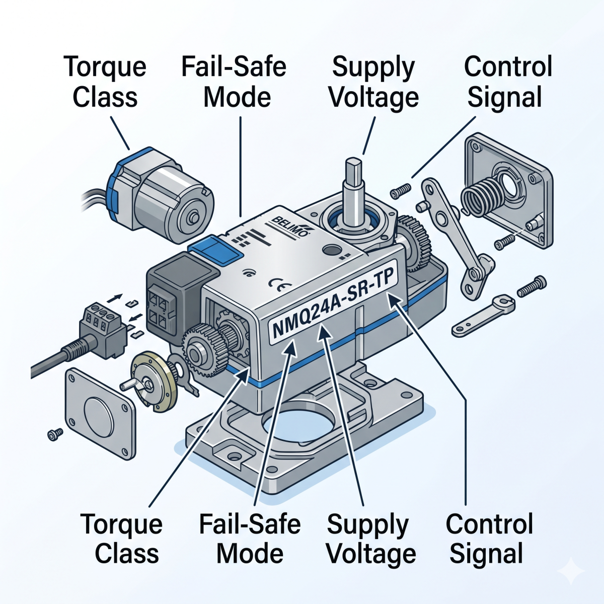
If you've ever stared at a Belimo part number like NMB24-MFT-T or R2025-B2 and wondered what each segment means, you're not alone. Belimo model numbers follow a precise alphanumeric logic — once you understand the system, you can read any Belimo code off a datasheet and know immediately what you're looking at: torque, fail-safe type, voltage, control signal, valve size.
This guide decodes the system end to end, covering damper actuators, control valves, and the most commonly specified variants used in Australian commercial HVAC and building automation projects.
Controls Traders stocks the full Belimo product range as an authorised Australian distributor. If you need to cross-reference a model or check availability, the Belimo brand page is the place to start.
The Belimo Naming Architecture — A Quick Overview
Belimo model numbers are not random. They encode, from left to right:
- Torque class (for actuators) or valve configuration (for valves)
- Fail-safe mode — spring return, non-spring return, or electronic fail-safe
- Configuration type — basic, flexible, or rotary valve mount
- Supply voltage
- Control signal type — indicated by the suffix after the dash
- Optional features — auxiliary switches, terminal blocks, communication protocols
Some positions are letters, some are numbers, and the suffixes add further layers. Work through each position in sequence and the code becomes readable in under a minute.
Damper Actuator Model Numbers Decoded
Position 1: Torque Class
The first letter of any Belimo damper actuator indicates how much torque it produces. This is the most critical spec — undersize the actuator and the damper won't close properly; oversize and you've wasted money and potentially damaged the damper linkage.
| First Letter | Torque | Typical Application |
|---|---|---|
| T | 2 Nm | Small zone dampers, VAV boxes |
| L | 5 Nm | Small to medium dampers |
| N | 10 Nm | Medium commercial dampers |
| A | 20 Nm | Large AHU dampers |
| G | 40 Nm | Very large dampers, multi-stack assemblies |
| E | Variable | Large or specialty applications |
As a rule of thumb, calculate 1 Nm per 1.5–2 m² of damper area, then select the next torque class up for safety margin. Tight-sealing dampers, cold climates, and ageing linkages all increase the effective torque requirement.
Position 2: Fail-Safe Mode
The second letter defines how the actuator behaves on power loss — critical for life safety applications and sequence-of-operations design.
- F — Spring return (fail-safe). An internal mechanical spring drives the actuator to a defined fail position (fully open or fully closed) when power is removed. Required for outdoor air intakes, fire mode interlocks, and any application where a defined fail position is mandatory.
- M — Non-spring return (modulating). The actuator holds its last commanded position on power loss. Standard for heating and cooling coil valves where position memory is acceptable and no life-safety requirement applies.
- K — Electronic fail-safe. Uses an onboard capacitor to drive the actuator to the fail position rather than a mechanical spring. Quieter and lighter than spring-return, but requires the capacitor to be charged.
This is why LF and LM are different products despite looking similar at first glance. An LF will spring-return on power loss; an LM will hold position.
Position 3: Configuration Type
- B — Basic or standard configuration
- X — Flexible or configurable (used with MFT units that can be field-programmed)
- R — Rotary valve mount (factory-installed linkage for direct coupling to valve bodies)
Voltage — The Middle Numbers
The digits following the configuration letter indicate supply voltage:
- 24 — 24 V AC/DC (most common in BAS panel applications)
- 120 — 120 V AC
- 230 — 230 V AC (common in Australian commercial installations)
- UP — Universal power supply (AC 24–240 V / DC 24–125 V) — the most flexible option, especially useful in retrofit projects where supply voltage at the panel is unknown
A full actuator code up to this point looks like: NMB24 — a 10 Nm, non-spring return, basic actuator running on 24 V.
Control Signal Suffixes
The suffix after the dash defines how the actuator receives its control signal:
- -3 — Floating (three-point) control. Separate open and close pulse signals drive the actuator motor. Simple, reliable, and requires no feedback signal. Suitable for two-position and coarse modulating applications.
- -SR — Proportional control via a 2–10 V DC input. Important: the "SR" does not stand for spring return — it refers to the signal range. This is one of the most common misreadings among engineers new to Belimo.
- -MFT — Multi-Function Technology. Field-programmable actuator configured via Belimo's PC-Tool software for floating, proportional (0–10 V), or other control modes. Supports BACnet MS/TP and Modbus RTU communication via a Belimo ZipLink or bus module. The preferred specification for intelligent BAS integrations.
Option Suffixes
- -S — One or more built-in auxiliary switches. Required when your sequence of operations needs a damper-open proof signal for fan interlock, or a BAS feedback input.
- -T — Terminal block wiring rather than a pre-attached cable. Useful where the actuator is field-wired directly into a BAS panel.
Putting It Together — A Full Example
NMB24-MFT-T
- N = 10 Nm torque
- M = Non-spring return (holds position on power loss)
- B = Basic configuration
- 24 = 24 V AC/DC supply
- MFT = Multi-Function Technology, field-programmable, BACnet/Modbus capable
- T = Terminal block wiring
If you're specifying damper actuators for AHUs or VAV systems, the MFT suffix gives you maximum flexibility for future reprogramming without changing hardware — a smart investment on any project that will run a modern BAS.
Fire and Smoke Actuator Model Numbers
Fire and smoke actuators follow the same base logic but are prefixed with FS to denote compliance with fire-rated damper requirements:
- FSLF — Fire/smoke, low torque (approximately 30 in-lb)
- FSNF — Fire/smoke, medium torque
- FSAF — Fire/smoke, high torque (approximately 180 in-lb)
These actuators are independently tested and certified for operation at elevated temperatures (up to 177°C / 350°F). Never substitute a standard damper actuator on a fire/smoke damper regardless of torque match — the independent certification is what matters, and the installation will not meet NCC or AS 1668 requirements without it.
Control Valve Model Numbers Decoded
Belimo valve model numbers encode valve type, pipe size, and — for pre-assembled units — the actuator pairing. The logic is separate from the actuator naming but equally systematic.
R-Series: Characterised Control Valves
The R2.. and R3.. series are characterised control valves for modulating control of chilled water, hot water, and condenser water circuits.
- R2 — 2-way characterised control valve
- R3 — 3-way characterised control valve
The digits following indicate DN (nominal bore) size:
| Model Code | DN Size | Common Application |
|---|---|---|
| R2015 | DN 15 (½") | Fan coil units, small terminal units |
| R2020 | DN 20 (¾") | Larger FCUs, small AHUs |
| R2025 | DN 25 (1") | AHU coils, medium capacity systems |
| R2032 | DN 32 (1¼") | Medium-large coils |
| R2040 | DN 40 (1½") | Large AHU coils |
| R2050 | DN 50 (2") | Large capacity coils, chiller connections |
Important: Valve sizing is based on Kv/Cv flow coefficient and system flow rate — not on pipe connection diameter alone. Oversizing a valve (selecting a larger Kv than required) causes the valve to run at very low percentage open, destroying control authority and making the system difficult to commission. Use Belimo's selection tool or the Kv calculation method at the design stage.
For fan coil unit and terminal unit control applications, the R2015 and R2020 characterised valves paired with a rotary actuator are the most common specification in Australian hotel and commercial projects.
B-Series: Pre-Assembled Ball Valve Units
The B2.. and B3.. series are factory-assembled valve and actuator combinations:
- B2 — 2-way ball valve assembly
- B3 — 3-way ball valve assembly
These arrive from the factory with a matched Belimo actuator already installed, which reduces installation time and the risk of mismatched torque selection. The actuator designation follows the valve body code and determines control type, voltage, and fail-safe behaviour.
If you're comparing control valve options for chilled or hot water systems, the B-series simplifies procurement and installation but offers less field-configuration flexibility than a separately mounted R-series valve with a chosen actuator.
Pressure-Independent Control Valves
Belimo's pressure-independent valve range uses distinct model designations:
- PICCV — Pressure independent characterised control valve. Integrates a differential pressure regulator, removing the need for separate manual balancing valves. Pre-set from the factory to the design flow.
- EPIV — Electronic pressure independent valve. Adds flow measurement capability via onboard electronics.
- Energy Valve (EV..) — Combines PICV function, energy metering, and BACnet/Modbus communication in a single device. Provides real-time coil delta-T monitoring and can detect fouled coils. Increasingly specified on large chilled and hot water distribution systems.
These products are specified at design stage and selected by maximum design flow (L/s or GPM), not by Kv. No manual commissioning of flow balancing is required after installation.
Common Ordering Mistakes to Avoid
1. Confusing -SR with spring return. The -SR suffix on a Belimo actuator means 2–10 V DC proportional signal, not spring return. For spring return, look at the second character — 'F' for spring return. An NM24-SR is a non-spring-return actuator with proportional control; an NF24-SR is spring return with proportional control.
2. Incorrect voltage specification. Ordering a 24 V actuator into a 230 V panel causes equipment damage and a field rework. Australian commercial installations commonly use 230 V panels — verify the panel supply voltage before specifying.
3. Torque undersizing. Default to the next torque class up from your calculated requirement. Tight-sealing dampers, cold climates, and ageing linkage hardware all increase effective torque demand beyond the theoretical calculation.
4. Sizing a valve by connection diameter rather than Kv. The pipe size printed on a valve does not determine whether it's right for your application. An oversized valve running at 5% open has very poor control authority. Calculate Kv from design flow and acceptable pressure drop.
5. Forgetting auxiliary switch requirements. If your sequence of operations requires a damper-open proof signal to enable a fan start, the base actuator will not provide it. Order the -S variant at design stage — retrofitting auxiliary switches in the field is difficult and usually requires a unit swap.
Frequently Asked Questions
What does the 'F' mean in Belimo model numbers like LF24 or NF24?
The 'F' in the second position indicates spring return (fail-safe) operation. When power is removed, an internal spring drives the actuator to its fail position — either fully open or fully closed depending on how the actuator is mounted and wired. This behaviour is distinct from 'M' (non-spring return — holds last position on power loss) and 'K' (electronic fail-safe — capacitor-driven return to fail position).
What is the difference between Belimo -3 and -SR control signal types?
The -3 suffix indicates floating (three-point) control: separate open and close pulse signals drive the actuator motor in each direction. The -SR suffix indicates proportional control via a 2–10 V DC input that positions the actuator continuously across its full stroke. Proportional control provides finer modulation and is preferred for chilled water and heating coil valve applications. Floating control is simpler, lower cost, and entirely adequate for on/off and two-position damper applications.
What does MFT mean on a Belimo actuator, and does it support BACnet?
MFT stands for Multi-Function Technology. MFT actuators are field-programmable via Belimo's PC-Tool software — control direction, signal range, fail position, and operating time can all be configured on site without hardware changes. When used with a Belimo ZipLink module or bus interface, MFT actuators support BACnet MS/TP and Modbus RTU communication, enabling full integration into a building automation system.
How do I size a Belimo R-series characterised control valve?
Size the valve by Kv (flow coefficient) value, not by pipe connection diameter. Calculate the required Kv from your coil design flow rate (L/s) and the acceptable pressure drop across the valve (typically 25–50% of the coil pressure drop for good control authority). Use Belimo's online selector tool or the formula Kv = Q / √ΔP to arrive at the correct model number. Always aim for a valve authority of 0.5 or above at design conditions.
Can a Belimo actuator be replaced without replacing the valve body?
Yes, for separately specified R-series valve and actuator combinations. Belimo actuators use a direct-coupled shaft interface that allows the actuator to be removed and replaced without disturbing the valve body or pipework. The replacement actuator must have equal or greater torque than the original and a compatible shaft interface. For B-series pre-assembled ball valve units, the valve and actuator are typically replaced as a complete unit since the assembly is factory-set.
Summary
Belimo model numbers are systematic, not arbitrary. Reading from left to right: torque class, fail-safe mode, configuration type, voltage, then control signal and options as suffixes. For valves, the series prefix tells you valve type and configuration, and the following digits give DN size or flow class.
Understanding the code means specifying correctly the first time, identifying cross-references quickly, and verifying that what arrives on site matches the design intent — a small investment that pays off every time a delivery note lands on the workbench.
Controls Traders is an authorised Belimo distributor in Australia. Browse the full Belimo product range or contact the team for selection support on your next project.

Fan Coil Unit Room Controllers: How to Choose the Right Thermostat for Hotel and Commercial FCUs

Fan coil unit (FCU) room controllers are the most common interface between building occupants and HVAC systems in hotels, apartments, offices and healthcare facilities across Australia. Choose the wrong one and you will spend months dealing with occupant complaints, energy waste and callbacks. Choose the right one and the system runs quietly in the background for a decade.
This guide covers the key decisions engineers, electrical contractors and facility managers need to make when specifying an FCU room controller — from system type and control signal through to brand selection and BMS integration.
What Is an FCU Room Controller?
An FCU room controller is a standalone thermostat or controller that manages the fan speed and valve position of a fan coil unit to maintain a set temperature in a room or zone. It reads the room temperature, compares it to the occupant setpoint, and signals the FCU fan and control valve to heat or cool as required.
Unlike full BMS controllers — which require programming, commissioning and network configuration — FCU room controllers are pre-configured for specific applications and designed for direct installation by electricians without specialist BMS expertise. That makes them the preferred choice for projects where room-level control needs to be straightforward and reliable.
2-Pipe vs 4-Pipe FCU Systems
Before specifying a room controller, you need to know whether the FCU system is 2-pipe or 4-pipe, as this determines which controller outputs you need.
- 2-pipe systems: One supply and one return pipe. The system runs either heating or cooling depending on the season, and the room controller manages a single 2-way or 3-way control valve. Common in older Australian commercial buildings and budget hotels.
- 4-pipe systems: Separate heating and cooling circuits. The room controller must manage two control valves — one for the cooling coil and one for the heating coil — plus the fan. This gives simultaneous heating and cooling capability and is standard in premium hotels and modern office buildings.
Some controllers handle both configurations, but check the output count and relay specifications carefully before assuming a single model will cover both applications.
Key Selection Criteria
1. Supply Voltage
Most FCU room controllers for commercial and hotel applications in Australia run at 230V AC, matching standard building wiring. Some 24V AC models exist — common in older Schneider/TAC installations — but the majority of new Australian projects use 230V controllers. Always confirm the electrical circuit design before selecting a controller.
2. Fan Speed Outputs
Standard FCUs run 2-speed or 3-speed fans. Your controller needs the matching number of relay outputs. A 3-speed controller on a 2-speed FCU is fine — you simply do not wire the third speed. The reverse is not workable without modifications.
3. Valve Output Type
This is where most specification errors occur. The three common output types are:
- On/Off (2-position): Opens or closes the valve fully. Simple and cost-effective, but causes temperature hunting in precise comfort applications. Suitable for low-demand zones or budget installations.
- 3-position (floating): Opens, closes, or holds the valve in position — more stable than on/off without requiring a modulating actuator. A good middle-ground for most commercial FCU applications.
- Modulating (0–10V or 4–20mA): Proportional control that positions the valve at any point between 0 and 100%. Best for tight temperature control and energy efficiency. Requires a compatible modulating valve actuator.
The controller output type and the actuator type must match. A modulating controller wired to an on/off actuator will still only open or close fully, regardless of the signal being sent.
4. Hotel vs Commercial Office Requirements
Hotel applications have specific requirements that standard commercial controllers do not always address:
- Lockable setpoint range — guests can adjust temperature within a band defined by management, typically ±2°C from a central setpoint
- Card-key input — the controller switches to an energy-saving setback mode when the guest key card is removed from the room
- Window contact input — the system reduces output or shuts off when a window or balcony door is open
- Guest-facing display — shows temperature in Celsius with no engineering or configuration menus accessible to guests
Purpose-built hotel room controllers like the Siemens RDF300 and RDG series address all of these out of the box. Using a standard commercial thermostat in a hotel without configuring the setpoint lock leads to guests pushing temperatures to extremes, defeating the building's energy management strategy and increasing operating costs.
5. BMS Integration
For projects that require room-level data in a building management system, consider controllers with BACnet or Modbus communication. These allow the BMS to read live room temperature, override setpoints centrally, and log occupancy and fault data.
Not every project needs this. Standalone controllers are the right choice when rooms operate independently. For hotels with property management system integration, or commercial buildings with centralised energy monitoring, communicating controllers justify the additional cost through operational savings.
FCU Room Controllers at Controls Traders
Controls Traders is an authorised distributor for Siemens, Schneider Electric, Smart Temp and Hevac. Our range covers the full spectrum from basic on/off hotel thermostats to fully communicating BACnet zone controllers, with stock held in Adelaide for fast Australia-wide delivery.
Siemens RDF and RDG Series
The Siemens RDF300 is our most popular FCU room controller. It runs at 230V AC, offers on/off or 3-position output, has an LCD display with occupant temperature adjustment, and includes multifunctional inputs for window contact, heat/cool changeover and external temperature sensor. It is flush-mounted to a standard rectangular conduit box (BS4662, 60.3mm fixing centres) — compatible with standard Australian electrical back boxes.
The RDF series suits 2-pipe and simple 4-pipe applications where proportional control is not required. For more complex hotel installations — where card-key switching, presence detection or wider programmability is needed — the Siemens RDG160T, RDG200T and RDG400 offer expanded I/O and configuration options.
Schneider SpaceLogic T900 and SE8000 Series
The Schneider SE8000 series and SpaceLogic T900 range are the right choice when BMS integration is required. These controllers communicate over BACnet MS/TP, support 4-pipe FCU configurations, and have configurable outputs for fan coil applications. They are commonly specified in commercial office buildings and larger hotel projects where room-level monitoring feeds into a central BMS or SCADA system.
Smart Temp
Smart Temp manufactures FCU room controllers and thermostats designed specifically for the Australian and New Zealand market. Their range is well-suited to education and healthcare facilities and is a popular choice with building services contractors who prefer locally-supported products.
Hevac
Hevac controllers cover single-stage and multi-stage heating and cooling control, suitable for simpler FCU and hydronic heating applications. The HTC-2 and HTC-4 are common in commercial and light industrial settings where a straightforward, reliable temperature controller is needed without network connectivity.
Quick Comparison
| Brand / Series | Application | System Type | Voltage | Key Feature |
|---|---|---|---|---|
| Siemens RDF300 | Hotel guest rooms, commercial FCU | 2-pipe & 4-pipe | 230V AC | Guest setpoint lock, card-key input, LCD display |
| Siemens RDG160T / RDG400 | Premium hotel, complex FCU | 2-pipe & 4-pipe | 230V AC | Extended I/O, programmable, window contact |
| Schneider SE8000 | Commercial offices, BMS projects | 4-pipe | 24V AC | BACnet MS/TP, configurable outputs |
| Schneider SpaceLogic T900 | Commercial & hotel BMS integration | 2-pipe & 4-pipe | 24V AC | BACnet, NFC commissioning |
| Smart Temp | Education, healthcare, commercial | 2-pipe | 230V AC | Australian designed, local support |
| Hevac HTC-2 / HTC-4 | Commercial, light industrial | 2-pipe heating | 230V AC | Simple, reliable, no BMS required |
Common Specification Mistakes
These are the most frequent issues we see at Controls Traders when projects are commissioning:
- Mismatched actuator and controller output: Specifying a modulating (0–10V) controller without confirming the valve actuator is also modulating. If the actuator is on/off, the valve will only open or close fully regardless of the control signal.
- No setpoint lock in hotel rooms: Installing a standard commercial thermostat in a hotel room without configuring the setpoint lock. Guests will always adjust temperatures to extremes, increasing energy costs and HVAC wear.
- Wrong conduit box standard: Not all European FCU controllers fit standard Australian rectangular back boxes without an adapter plate. Check mounting dimensions (standard Australian fixing is 60.3mm centres) before specifying.
- Voltage mismatch: Installing a 24V AC controller on a 230V AC circuit. Always confirm the electrical design before selecting a controller. If 24V is required and the existing circuit is 230V, a step-down transformer is needed.
- Selecting a 2-pipe controller for a 4-pipe system: A 2-pipe controller has one valve output and cannot independently manage separate heating and cooling valves. This results in either simultaneous heating and cooling or loss of one function entirely.
Controls Traders stocks the complete Siemens RDF and RDG series, Schneider SpaceLogic T900 and SE8000, Smart Temp and Hevac FCU room controller ranges. As an authorised distributor for all brands, we carry genuine products with full manufacturer support, stocked in Adelaide for Australia-wide delivery.
Browse our stand-alone controllers and thermostats range online, or call our technical team on 1300 740 140 for application-specific advice.
Frequently Asked Questions
What is the difference between an FCU room controller and a standard thermostat?
An FCU room controller is specifically designed to manage both the fan speeds and the control valve of a fan coil unit. A standard thermostat typically only switches heating or cooling on or off. FCU controllers have multiple relay outputs for fan speed stages and separate valve outputs for heating and cooling, making them purpose-built for fan coil applications in commercial and hotel buildings.
Can I use a 2-pipe FCU controller on a 4-pipe system?
No. A 2-pipe controller only has one valve output and cannot independently control the heating and cooling valves required in a 4-pipe system. Using the wrong controller will result in either simultaneous heating and cooling, or a complete loss of one function. Always confirm whether the system is 2-pipe or 4-pipe before specifying a controller.
What is the best FCU room controller for hotel guest rooms in Australia?
For most Australian hotel applications, the Siemens RDF300 or RDG series offers the right balance of features, reliability, and ease of installation. Key hotel-specific requirements include a lockable setpoint range, card-key input for occupancy switching, and a guest-friendly display without accessible engineering menus. Siemens' RDF and RDG controllers support all of these natively and are stocked by Controls Traders in Adelaide.
Does an FCU room controller need to connect to a BMS?
Not necessarily. Many FCU room controllers operate as standalone devices with no network connection, which is sufficient for smaller buildings or projects where room-level data is not required centrally. For hotels with property management system integration, or commercial buildings with centralised energy monitoring, BACnet-communicating controllers like the Schneider SE8000 or SpaceLogic T900 allow the BMS to read temperature, override setpoints, and log occupancy and fault data.
What supply voltage do FCU room controllers use in Australia?
The majority of FCU room controllers in Australian commercial and hotel applications run at 230V AC, which is the standard Australian building supply voltage. Some older systems and European product ranges use 24V AC, which requires a step-down transformer. Always confirm the supply voltage from the electrical drawings before selecting a controller.
What is the difference between on/off, 3-position and modulating valve outputs on an FCU controller?
On/off control opens or closes the valve completely, which is simple but causes temperature fluctuations. 3-position (floating) control can open, close, or hold the valve in position, giving more stable control without needing a modulating actuator. Modulating (0-10V) control positions the valve proportionally between 0 and 100%, providing the most precise temperature control but requiring a compatible modulating actuator on the valve body.
How do I know if my FCU system is 2-pipe or 4-pipe?
Count the pipes connected to the fan coil unit. A 2-pipe system has one supply pipe and one return pipe — the same circuit provides either heating or cooling depending on the season. A 4-pipe system has two supply pipes and two return pipes — one circuit for chilled water (cooling) and a separate circuit for hot water (heating). If you are unsure, check the mechanical services drawings or the FCU manufacturer's documentation.

Advanced Troubleshooting: Common Symptoms of Faulty HVAC Sensors
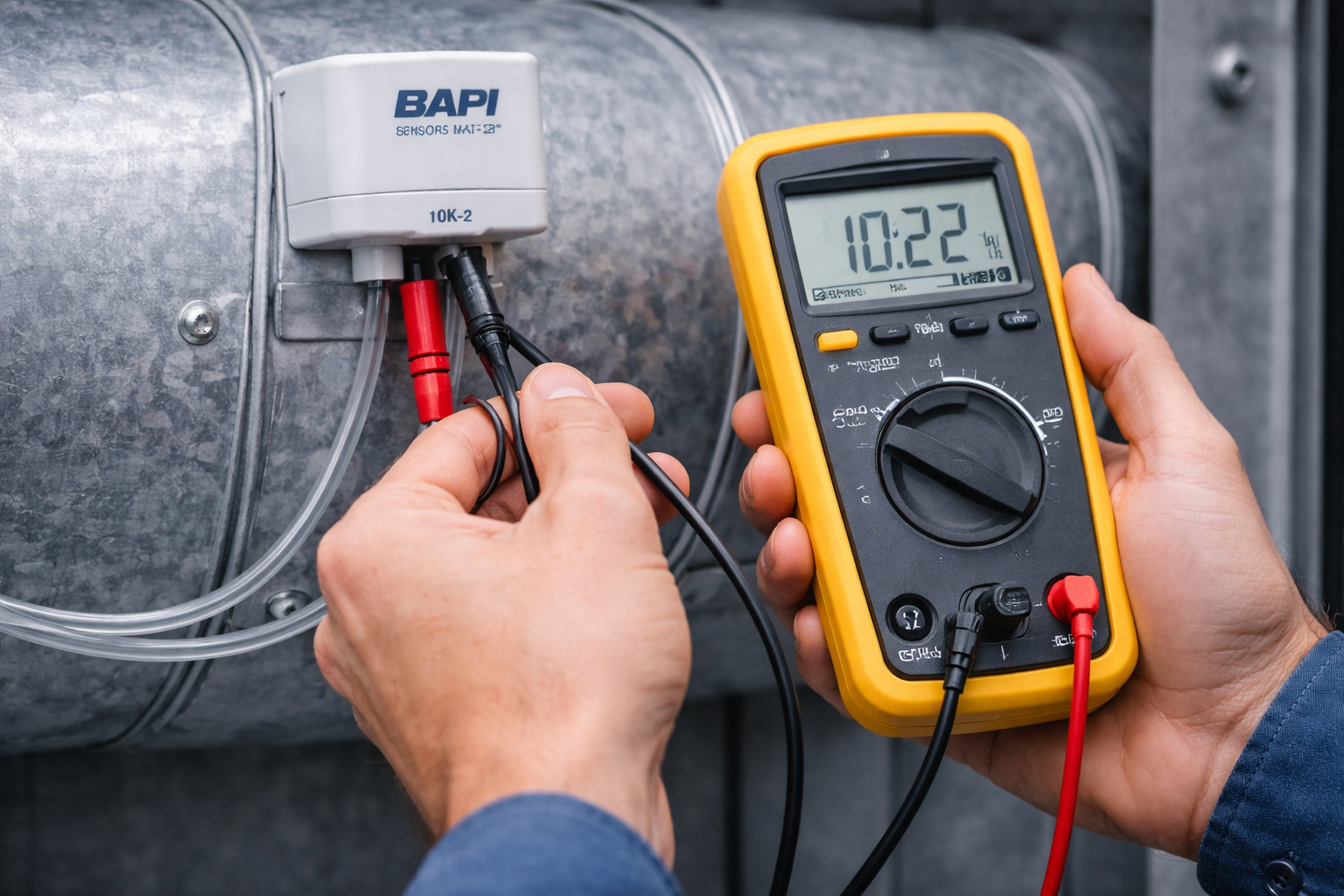
In a Building Management System (BMS), your mechanical plant is only as smart as the data it receives. If a chiller plant receives bad data from a faulty return water sensor, it will operate inefficiently—no matter how advanced the controller logic is.
When building occupants complain about stuffy rooms or freezing drafts, the mechanical equipment is often blamed first. However, the root cause is frequently sensor failure.
At Controls Traders, we supply premium Sensors & Transducers across Australia. Drawing on our 40 years of experience, here is an advanced troubleshooting guide to identifying the symptoms of faulty HVAC sensors.
Symptom 1: Massive Temperature Offsets (-40°C or +120°C)
If your BMS is suddenly reading an impossible temperature (like -40°C in an office or +120°C in a chilled water line), the issue is almost certainly electrical, not environmental.
The Cause:
- Open Circuit / Short Circuit: For standard 10k thermistors, an open circuit (a cut wire) will typically read at the extreme bottom of the controller's scale (e.g., -40°C). A short circuit (wires touching) will read at the absolute maximum.
- Sensor Type Mismatch: If a technician wires a 10k Type 3 sensor into a controller programmed to read a 10k Type 2 curve, the temperature offset will be severe. Always verify the thermistor curve matches the software configuration.
Symptom 2: Sluggish or "Hunting" Control Loops
If the room temperature swings wildly from hot to cold, or the chilled water supply temperature oscillates, the sensor may be suffering from thermal lag.
The Cause:
- Missing Thermal Paste: If a pipe immersion sensor is placed into a thermowell without thermal conductive paste, the air gap acts as an insulator. The water temperature changes, but the sensor takes 15 minutes to register it, causing the controller to overreact.
- Poor Placement: A Room Sensor mounted behind a bookshelf or a Duct Sensor placed in a dead-zone of the AHU will not see the airflow, resulting in sluggish response times.
Symptom 3: CO₂ and Humidity "Drift"
Unlike standard thermistors (which rarely drift), Indoor Air Quality (IAQ) sensors—like CO₂ and Humidity transducers—contain active sensing elements that can degrade or drift over time.
The Cause:
- Loss of Calibration: If the VAV box is pumping in 100% outside air but the room is empty, the CO₂ sensor has likely drifted upwards. High-quality sensors (like those from BAPI or Siemens) feature Automatic Background Calibration (ABC) to re-zero themselves based on overnight baseline levels. If a building is occupied 24/7, this ABC logic can fail, requiring manual calibration or replacement.
- Contamination: Humidity sensors placed in aggressive environments (like pools or outside air intakes) can suffer from chemical or moisture contamination on the sensing polymer, skewing the relative humidity reading permanently.
What to Do When a Sensor Fails
If a sensor has drifted beyond repair or suffered water ingress, it must be replaced to restore building efficiency.
Standardizing your site with reliable, high-quality sensors from reputable brands reduces the frequency of these service calls. Controls Traders warehouses a massive inventory of Sensors & Transducers locally in Adelaide.
Whether you need a replacement duct probe or a highly accurate room unit, we offer fast shipping Australia-wide. Call our support team on 1300 740 140 for cross-referencing and technical advice.
Frequently Asked Questions
How do I know if my HVAC temperature sensor has an open circuit or short circuit?
For a 10k thermistor, use a multimeter set to resistance (ohms). At room temperature (~25°C), a healthy 10k-2 sensor will read approximately 10,000 ohms. A reading of OL (overload/infinite resistance) indicates an open circuit — the wire or sensor element is broken. A reading of near 0 ohms indicates a short circuit — the wires are touching. Both faults produce extreme temperature readings on the BMS (typically -40°C or maximum scale).
What is Automatic Background Calibration (ABC) in CO₂ sensors?
ABC is a self-calibration feature in CO₂ sensors that assumes the lowest CO₂ reading recorded over a rolling period (typically 1–2 weeks) represents clean outdoor air (~400 ppm). The sensor uses this baseline to correct for drift. ABC works well in buildings that are regularly unoccupied overnight. However, in buildings occupied 24/7 — like hospitals or data centres — CO₂ never drops to baseline, and ABC logic will gradually drift the calibration upward, requiring manual recalibration or replacement.
Why does my room temperature sensor read correctly at times but drift at others?
Intermittent readings usually point to a loose connection or a partially broken wire that makes and breaks contact with vibration or temperature changes. Check terminal screws at both the sensor and controller ends first. If wiring checks out, the thermistor bead itself may have a hairline fracture — common in older sensors that have experienced physical shock — and the sensor will need replacing.
Can a humidity sensor be repaired after moisture or chemical contamination?
Generally no. Humidity sensors use a polymer film that absorbs and releases moisture to measure relative humidity. Chemical contamination or prolonged exposure to saturated air (RH > 95%) permanently alters the polymer, skewing the reading. Some manufacturers offer a bake-out recovery process for mild contamination, but in most cases, a contaminated humidity sensor must be replaced. Controls Traders stocks replacement room sensors with integrated humidity sensing for fast dispatch from Adelaide.
How often should HVAC sensors be recalibrated or replaced?
Standard thermistors (10k-2) rarely need recalibration and can last 15+ years if installed correctly. CO₂ sensors typically require recalibration every 2–3 years and replacement every 5–7 years depending on the environment. Humidity sensors in clean indoor environments can last 7–10 years, but those exposed to outdoor air, pool environments, or chemical fumes may need replacement every 2–3 years. Differential pressure sensors should be verified annually against a calibrated reference.
Read more
When and How to Use HVAC Voltage Converters
When and How to Use HVAC Voltage Converters
Upgrading or repairing commercial HVAC systems rarely involves a clean slate. More often than not, controls technicians are forced to integrate modern, low-voltage digital components into older, high-voltage mechanical switchboards.
This creates an immediate electrical conflict. If you try to wire a modern 24V DC actuator into a legacy 240V AC control circuit, the result will be catastrophic failure.
To bridge this gap safely, technicians rely on Voltage Converters. At Controls Traders, we supply the essential Switches & Electrical gear required to make modern retrofits possible.
What is an HVAC Voltage Converter?
A voltage converter (or power supply/transformer) is an electrical component that steps down, steps up, or rectifies power from one format to another.
In the HVAC and building automation industry, they are typically used to step high mains voltage down to the safe, low voltages required by BMS controllers, sensors, and field devices.
Common Scenarios for Voltage Conversion
1. Stepping Down 240VAC to 24VAC (The Standard Retrofit) Most modern building automation controllers and smart actuators—like those from Belimo or Siemens—run on 24V AC or DC. If you are retrofitting a plant room that previously relied on 240V pneumatic-electric hybrid controls, you must install a step-down transformer to provide a safe 24VAC power bus for your new Valve Actuators.
2. Converting 24VAC to 24VDC (Rectification) While many HVAC actuators will accept both 24V AC and DC, certain specialized sensors (especially some older 4-20mA loop-powered transmitters) strictly require 24V Direct Current (DC). If your main control panel only has a 24VAC transformer, you need a DC converter module to rectify the AC power into a clean DC output for these sensitive instruments.
3. Isolating Control Circuits Even if the voltage matches, isolation transformers or specific converters are sometimes used to electrically isolate a sensitive BMS controller from "noisy" field devices like large contactors or VSDs, preventing electrical feedback from crashing the microprocessor.
How to Size Your Voltage Converter
When selecting a Power Supply or voltage converter, you must calculate the total load of the devices it will power.
- Check the VA Rating: Add up the Volt-Ampere (VA) or Wattage ratings of all the controllers, sensors, and actuators connected to the circuit.
- Account for Inrush: Actuators (especially spring-return models) can draw significantly more power when they first start moving than when they are resting. Always size your converter or transformer with at least a 20-30% safety margin to handle this inrush current.
Available at Controls Traders
Wiring mismatched voltages is one of the most common causes of equipment failure during commissioning. Ensuring you have the correct power conditioning equipment is critical.
Controls Traders, based in Adelaide, stocks a wide range of Voltage Converters and DIN-rail mountable power supplies suited for industrial HVAC environments.
Explore our full range of Switches & Electrical products online, and enjoy fast, Australia-wide shipping on all orders.
Frequently Asked Questions
What is the difference between a transformer and a voltage converter in HVAC?
In HVAC, these terms are often used interchangeably, but technically a transformer steps voltage up or down while keeping the power as AC (e.g., 240VAC to 24VAC). A voltage converter is a broader term that can also include DC power supplies (rectifiers), which convert AC to DC. Most BMS panels use both — a step-down transformer to create a 24VAC bus, and DC power supply modules for devices that require 24VDC.
How do I calculate what size transformer or power supply I need?
Add up the VA (Volt-Ampere) or Watt ratings of all devices the transformer will power — controllers, actuators, sensors, relays. Then add a 20–30% safety margin to handle actuator inrush current when spring-return models first energize. For example, if your total device load is 80VA, select a transformer rated for at least 100–120VA. Undersizing is one of the most common causes of BMS panel faults during commissioning.
Can I run both 24VAC and 24VDC devices from the same transformer?
You can run a DC converter module off the same transformer to derive 24VDC from the 24VAC bus, but the two circuits should be electrically isolated. Mixing AC and DC on the same wiring terminals will damage 24VDC-only devices. Always use separate terminal rails and clearly label AC and DC circuits in your panel documentation.
What is electrical isolation and when is it needed in HVAC panels?
Electrical isolation separates two circuits so that electrical noise or faults in one cannot affect the other. It is commonly used to protect sensitive BMS microprocessors from noise generated by large contactors, variable speed drives, or inductive loads switching on and off nearby. An isolation transformer or an optically isolated DC supply module provides this protection.
Where can I buy HVAC voltage converters and power supplies in Australia?
Controls Traders stocks a full range of voltage converters and power supplies suited for HVAC control panel applications from our Adelaide warehouse, with fast Australia-wide delivery. Call 1300 740 140 for sizing advice or browse our Switches & Electrical catalogue online.
Read more
Maximizing Accuracy with DP Sensors and Air Gauge Accessory Kits
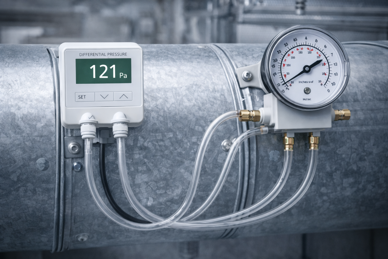
Maximizing Accuracy with DP Sensors and Air Gauge Accessory Kits
In the realm of building automation, while temperature sensors dictate comfort, pressure sensors dictate safety and mechanical efficiency.
Differential Pressure (DP) sensors are the silent workhorses of the plant room. They allow the Building Management System (BMS) to "feel" the resistance in the ductwork, providing the critical data needed to ramp up Variable Speed Drives (VSDs) or trigger maintenance alarms.
At Controls Traders, we stock high-accuracy air pressure sensors from brands like BAPI and Schneider Electric, alongside the necessary hardware to install them. Here is a guide on maximizing your airside accuracy.
Why Monitor Differential Pressure?
An air DP sensor measures the difference in pressure between two distinct points and outputs an electrical signal (like 0-10V) to the BMS. There are two primary applications in HVAC:
1. Filter Monitoring: As Air Handling Unit (AHU) filters accumulate dust, the pressure drops significantly across the filter bank. By placing the "High" port of the sensor before the filter and the "Low" port after the filter, the BMS can monitor this resistance. Once it hits a critical threshold (e.g., 150 Pascals), the system flags a "Dirty Filter" alarm, ensuring maintenance is driven by actual data rather than a calendar.
2. Duct Static Pressure Control: In a VAV (Variable Air Volume) system, as terminal boxes open and close, the pressure in the main supply duct fluctuates. A static pressure sensor—typically installed two-thirds of the way down the main duct—monitors this. If pressure drops, the BMS tells the supply fan to speed up; if it rises, the fan slows down, saving massive amounts of fan energy.
The Role of Air Gauge Accessory Kits
A high-quality sensor is useless if it cannot properly interface with the air stream. This is where the Air Gauge Accessory Kit comes into play.
These kits typically include the clear pneumatic tubing, mounting brackets, and the static pressure probes required to cleanly penetrate the ductwork.
- Accurate Sampling: A proper static pressure probe (often shaped like a pitot tube) ensures that the sensor is measuring the true static pressure of the duct, rather than being skewed by the velocity of the air rushing past the hole.
- Analog Verification: In many critical environments (like hospitals), an analog visual air gauge (like a Magnehelic) is mounted on the outside of the AHU alongside the digital BMS sensor, allowing technicians to verify pressure drops instantly during walk-arounds.
Selecting the Right Sensor
When sourcing a DP sensor, ensure you select the correct pressure range.
- For filter monitoring, a low-range sensor (e.g., 0-250 Pa) is usually sufficient.
- For main supply duct static pressure, a higher range (e.g., 0-500 Pa or 0-1000 Pa) may be required.
- Many of the premium Sensors & Transducers we stock feature field-selectable ranges, allowing you to stock one part number in your van that can adapt to multiple on-site applications.
Fast Delivery Across Australia
Don't let a missing accessory kit or a faulty pressure sensor delay your commissioning. Controls Traders warehouses a full range of Sensors & Transducers, including high-grade DP sensors and accessory kits, in our Adelaide facility.
Browse our catalog online or call our team on 1300 740 140 for expert selection advice and fast Australia-wide shipping.
-------------------------------------------
Frequently Asked Questions
What is the difference between an air DP sensor and a liquid DP sensor?
Air DP sensors (dry media) measure pressure differences in ductwork — typically in Pascals (Pa) — and are used for filter monitoring and duct static pressure control. Liquid DP sensors (wet media) measure pressure drops across pumps, chillers, and valves in hydronic systems, usually reading in kPa or Bar. The two types are not interchangeable — using a dry media sensor on a liquid application will damage or destroy it.
What pressure range should I select for a filter monitoring DP sensor?
For standard AHU filter banks, a 0–250 Pa sensor is typically sufficient. A clean filter will read close to 0 Pa, and you would set the BMS alarm threshold at around 150–200 Pa to flag a dirty filter before it causes significant airflow restriction. If your filters are coarser or your system runs at higher face velocities, a 0–500 Pa range may be more appropriate.
Where should a duct static pressure sensor be installed?
The standard practice is to install the static pressure sensor approximately two-thirds of the way down the longest main supply duct run, downstream of the main branch take-offs. This location represents the most challenging point for the fan to maintain pressure. Installing it too close to the fan will cause the BMS to react to local turbulence rather than true system pressure, leading to unstable fan speed control.
What is a Magnehelic gauge and how does it work alongside a BMS sensor?
A Magnehelic is an analog visual differential pressure gauge that uses a diaphragm and a magnetically linked pointer to display pressure. In critical environments like hospitals and cleanrooms, a Magnehelic is mounted on the outside of the AHU alongside the digital BMS sensor, giving technicians an instant visual pressure reading during walk-arounds without needing to log into the BMS. It serves as both a verification tool and a backup indicator.
Can a single DP sensor be used for both filter monitoring and duct static control?
No — these are two separate measurement points requiring separate sensors. Filter monitoring measures the pressure drop across the filter bank (between the dirty and clean sides of the filter). Duct static pressure control measures the pressure in the supply duct downstream of the fan and coils. Both are important, both require their own sensor and pneumatic connections, and both are typically wired to separate BMS inputs.
Read more
How to Wire ACI Current Switches and Schneider 24VAC Relays
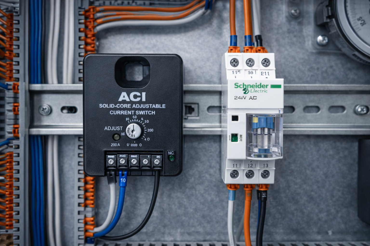
In commercial HVAC control panels, the Building Management System (BMS) relies on two critical functions to operate mechanical equipment safely: command (telling a device to start) and feedback (confirming it is actually running).
To achieve this, panel builders rely heavily on relays and current switches. At Controls Traders, we supply premium electrical components, including the highly sought-after Automated Components Inc (ACI) current switches and Schneider Electric relays.
Here is a practical guide on how these two essential components work together in a typical HVAC panel and best practices for wiring them.
The Role of the Schneider 24VAC Relay (The Command)
A BMS controller typically outputs a low-voltage (24VAC or 24VDC) signal. However, the exhaust fan or pump you want to start likely requires 240VAC or 415VAC. You cannot wire a high-voltage fan directly to a low-voltage controller without destroying it.
The Schneider 24VAC 2-Pole Relay acts as the isolation bridge.
- How it works: The BMS sends a 24VAC signal to the relay coil. This electromagnetically pulls the contacts closed.
- The Wiring: The high-voltage field wiring (e.g., the 240V fan start circuit) is wired through the "Normally Open" (NO) contacts of the relay. When the BMS energizes the relay, the high-voltage circuit completes, and the fan starts.
- Why Schneider? Schneider Electric relays are known for their industrial durability and reliable DIN-rail mounting bases, making panel layouts clean and easy to troubleshoot.
The Role of the ACI Current Switch (The Feedback)
Just because the BMS commanded the relay to close does not mean the fan is moving air. A belt could be snapped, or a local isolator could be turned off. This is where "Proof of Flow" is required.
The ACI Solid Core Adjustable Current Switch provides this proof.
- How it works: You pass one of the live high-voltage wires feeding the fan motor through the center (the "core") of the ACI current switch. The switch senses the magnetic field generated by the current flowing to the motor.
- The Wiring: The output terminals of the ACI switch are wired back to a Digital Input (DI) on the BMS controller.
- Adjustable vs. Fixed: An adjustable current switch is highly recommended because you can dial in the exact amperage threshold. If a fan belt snaps, the motor still spins but draws less current (because there is no load). By calibrating the ACI switch to trip just below the normal operating load, the BMS will instantly detect the broken belt and trigger an alarm.
Best Practices for Panel Builders
- Keep Voltages Separated: Always physically separate your low-voltage BMS wiring from your 240V/415V field wiring inside the panel to prevent electrical interference and ensure technician safety.
- Use DIN Rail Organization: Mount your Relays and any necessary 24V Power Supplies cleanly on DIN rails.
- Looping for Low Amperage: If the motor you are monitoring draws a very small amount of current (e.g., less than the minimum sensing threshold of the ACI switch), you can loop the live wire through the solid core two or three times to artificially multiply the current reading.
Source Your Electrical Controls Locally
Sourcing reliable control panel parts shouldn't hold up your manufacturing schedule. Controls Traders, based in Stepney, South Australia, warehouses a massive range of Switches & Electrical components.
Whether you need a box of Schneider relays or ACI adjustable current switches, we offer fast, Australia-wide delivery. Browse our range online or call us on 1300 740 140 for project pricing.
Frequently Asked Questions
What is the difference between a relay and a contactor in HVAC control panels?
A relay is a smaller switching device typically used for low-to-medium current loads — such as starting a single fan or signalling a control circuit. A contactor is a heavier-duty switching device designed for high-current loads like large motors, chillers, or three-phase pump starters. In BMS panels, relays handle the command interface between the low-voltage controller and the high-voltage field circuit, while contactors are usually found in the motor control centre (MCC).
Why use an adjustable current switch instead of a fixed one?
An adjustable current switch lets you set the exact amperage trip point to match the motor’s normal operating load. This is critical for detecting broken belts — a fan motor with a snapped belt still spins and draws current, but at a lower level than normal. A fixed switch may not detect this subtle drop, whereas an ACI adjustable current switch can be calibrated to trip below the unloaded motor current, triggering an alarm immediately.
Can I use the same relay for both 24VAC and 24VDC?
Not necessarily — relay coils are rated for specific voltage types. A relay rated for 24VAC may not pick up reliably on 24VDC, and vice versa. Always check the coil voltage specification on the relay datasheet before wiring. Controls Traders stocks both AC and DC variants of common HVAC relays — call 1300 740 140 to confirm the correct model for your application.
How do I loop a wire through an ACI current switch for low-amperage motors?
If the motor draws less current than the minimum sensing threshold of the ACI switch, simply loop the live supply wire through the solid core multiple times. Each additional loop effectively multiplies the sensed current by the number of passes. For example, three loops through the core triples the apparent current reading, allowing the switch to detect very small motors reliably.
Where can I buy ACI current switches and Schneider relays in Australia?
Controls Traders stocks ACI adjustable current switches and Schneider Electric relays from our Adelaide warehouse for fast Australia-wide delivery. Browse our Switches & Electrical range online or call 1300 740 140 for bulk project pricing.
Read more
The Complete Guide to BAPI 10K-2 Sensors: Room, Duct, and Immersion
.png) The Complete Guide to BAPI 10K-2 Sensors: Room, Duct, and Immersion
The Complete Guide to BAPI 10K-2 Sensors: Room, Duct, and Immersion
In the world of Building Management Systems (BMS), the 10k Type 2 thermistor is the undisputed industry standard. And when Australian integrators look for reliable, high-quality 10k-2 sensors, they overwhelmingly turn to BAPI.
A thermistor is an NTC (Negative Temperature Coefficient) device, meaning that as the temperature in the room or duct rises, the electrical resistance of the sensor drops. This provides a highly sensitive, cost-effective signal that almost every BMS controller on the market can read natively.
At Controls Traders, BAPI 10K-2 sensors are consistently among our top-performing products. Here is a complete guide to the three most critical BAPI 10K-2 form factors and where to apply them.
1. BAPI 10K-2 Quantum Room Sensor
The Quantum Room Sensor is designed for the occupied space. It features a modern, clean aesthetic that blends into high-end office environments while providing rapid response to changing heat loads.
Best Application: Standard office VAV zones, meeting rooms, and corridors. Because room sensors are exposed to the ambient environment, the BAPI Quantum housing is designed to allow excellent airflow over the 10k-2 thermistor bead, ensuring the BMS doesn't lag behind the actual room temperature.
2. BAPI 10K-2 Duct Temperature Sensor
Monitoring the air inside your ductwork is critical for controlling Air Handling Units (AHUs). BAPI provides robust Duct Sensors equipped with the 10k-2 thermistor.
Best Application:
- Rigid Probes: Ideal for supply air or small branch ducts where the air is well-mixed.
- Averaging Sensors: For large AHU mixed-air plenums. BAPI averaging sensors stretch across the duct to measure multiple points, preventing the BMS from reacting to isolated streaks of freezing outside air.
3. BAPI 10K-2 Immersion Temperature Sensor
Water is the lifeblood of central HVAC plants. The BAPI Immersion Sensor is built to sit directly in the fluid flow to measure chilled or heating water.
Best Application: Chiller supplies, boiler returns, and condenser water loops. These sensors are inserted into a stainless steel or brass thermowell. Pro Tip: Always use thermal paste when inserting the BAPI sensor into the well to eliminate insulating air gaps and ensure a lightning-fast response time.
Why Buy BAPI from Controls Traders?
Using an incorrect sensor curve (like wiring a 10k-2 sensor into a controller programmed for a 10k-3) will result in massive temperature offsets and system failure. Standardization is key.
By standardizing your site on the BAPI 10K-2 range, you ensure uniform accuracy from the chiller plant to the boardroom.
Controls Traders warehouses a massive inventory of Sensors & Transducers, including the full BAPI 10K-2 Quantum, Duct, and Immersion lines. Located in Adelaide, we provide fast, Australia-wide shipping so you can keep your commissioning schedule on track.
Browse our BAPI range online today or call 1300 740 140 for technical selection advice.
Frequently Asked Questions
What is a 10k Type 2 thermistor?
A 10k Type 2 (10k-2) thermistor is an NTC (Negative Temperature Coefficient) resistive temperature sensor with a nominal resistance of 10,000 ohms at 25°C. As temperature increases, resistance decreases. It is the most widely used thermistor curve in building automation, natively supported by virtually all major BMS controller brands. The "Type 2" refers to the specific resistance-temperature curve — it is not interchangeable with Type 3 without reconfiguring the controller software.
What happens if I wire a 10k-2 sensor into a controller configured for 10k-3?
The BMS will still receive a signal, but the temperature reading will be significantly offset — often by 5°C or more depending on the operating range. This will cause the controller to over-cool or over-heat the space, wasting energy and generating comfort complaints. Always verify the thermistor curve in the controller configuration matches the sensor you are installing.
What is the difference between a BAPI rigid probe and an averaging duct sensor?
A rigid probe inserts into the duct at a single point and is best used in small, well-mixed ducts like supply air branches. An averaging sensor stretches across the full width of the duct, measuring at multiple points simultaneously. Averaging sensors are essential in large AHU mixed-air plenums where cold outside air and warm return air can create significant temperature stratification — a single-point probe in that environment will give a misleading reading.
Why use thermal paste with an immersion sensor thermowell?
Without thermal paste, an air gap forms between the sensor tip and the inside of the thermowell. Air is a poor conductor of heat, which creates thermal lag — the water temperature changes, but the sensor takes many minutes to register the shift. This delay causes the controller to overreact and hunt. Filling the gap with thermal conductive paste ensures the sensor responds almost instantaneously to changes in fluid temperature.
Where can I buy BAPI sensors in Australia?
Controls Traders stocks the full BAPI 10K-2 sensor range — including Quantum room sensors, duct probes, averaging elements, and immersion sensors — from our Adelaide warehouse with fast Australia-wide delivery. Call 1300 740 140 for technical advice and project pricing.
Read more
A Technical Guide to the Siemens RDF300 Room Sensor
When it comes to commercial building automation, the room sensor is often the only piece of the HVAC system that the tenant actually sees. It needs to be accurate enough for the BMS to maintain tight control, yet aesthetically pleasing enough to satisfy architects.
The Siemens RDF300 has emerged as one of the most sought-after room units in the Australian market. It perfectly bridges the gap between industrial-grade reliability and modern commercial design.
As a trusted supplier of Siemens controls, Controls Traders offers this deep dive into why the RDF300 is a top choice for modern office fit-outs and VAV zone control.
Accuracy Meets Aesthetics
In premium office spaces, bulky, outdated thermostats are no longer acceptable. The Siemens RDF300 is a flush-mount room sensor designed to sit cleanly on the wall, providing a sleek, low-profile interface.
But beneath the modern exterior is highly sensitive sensing technology. The unit provides dual monitoring:
- Temperature: Providing the primary variable required for zone cooling and heating loops.
- Humidity: Essential for maintaining occupant comfort and preventing moisture issues in the building envelope.
By combining both temperature and humidity sensing into a single housing, installers reduce wall clutter and cut their cabling time in half.
Seamless BMS Integration
Siemens is renowned globally as an industrial powerhouse, and their field devices are built for seamless integration into high-level networks.
The data collected by the RDF300 doesn't just sit on the wall; it is fed back to your central controllers. Depending on the specific configuration of your DDC network, Siemens units utilize standard industry signals to communicate effortlessly with your existing BMS, ensuring that the plant room reacts instantly to the actual conditions inside the occupied space.
Application in Modern HVAC
The RDF300 is perfectly suited for dynamic building environments:
- VAV Zones: Providing rapid response to changing occupant loads in open-plan offices.
- Fan Coil Units (FCUs): Integrating with Valve Actuators to regulate chilled water flow precisely to the zone.
- Healthcare & Labs: Where strict humidity and temperature thresholds must be monitored constantly.
Available Now at Controls Traders
Whether you are standardizing a new multi-story build or replacing a drifting sensor in a legacy system, sourcing genuine Siemens hardware quickly is critical.
Controls Traders warehouses a massive inventory of Room Sensors, including the highly sought-after Siemens RDF300 series. Located in Adelaide, we bypass international supply chain delays, offering rapid, Australia-wide shipping to keep your projects on schedule.
Browse our full Siemens catalogue online or call our team on 1300 740 140 for project pricing.
Frequently Asked Questions
What does the Siemens RDF300 measure?
The Siemens RDF300 is a dual-function room sensor that measures both temperature and relative humidity simultaneously. It is designed as a flush-mount wall unit for commercial spaces, feeding both variables back to the BMS via standard industry signals for use in zone control, fan coil unit regulation, and humidity monitoring applications.
What BMS systems is the Siemens RDF300 compatible with?
The RDF300 uses standard analog output signals compatible with most major DDC controllers including Siemens, iSMA, Schneider, and EasyIO. The exact signal type (e.g. 0-10V, NTC thermistor) depends on the specific RDF300 variant — Controls Traders' technical team can advise on the correct model for your controller. Call 1300 740 140 for compatibility guidance.
Can the Siemens RDF300 be used for VAV zone control?
Yes — the RDF300 is specifically well-suited for VAV zone control in open-plan offices and meeting rooms. Its fast thermal response allows the BMS to react quickly to changing occupant loads, ensuring the VAV box modulates accurately to maintain setpoint.
Is the Siemens RDF300 suitable for healthcare or laboratory environments?
Yes. The dual temperature and humidity monitoring capability makes the RDF300 a strong choice for healthcare facilities and laboratories where strict environmental thresholds must be maintained continuously. For critical environments, always verify the specific accuracy and output specifications of the model against your project requirements.
Where can I buy genuine Siemens RDF300 sensors in Australia?
Controls Traders stocks genuine Siemens room sensors including the RDF300 series from our Adelaide warehouse, with fast Australia-wide delivery. Call 1300 740 140 or browse our Siemens catalogue online for current stock and project pricing.
Read more
How HVAC Flow Meters Improve Chilled Water System Efficiency
You cannot optimize what you cannot measure. For facility managers and HVAC engineers operating large chilled water plants, true energy efficiency goes beyond simply installing a Variable Speed Drive (VSD) or upgrading a chiller. To achieve maximum efficiency and maintain a high Delta T (ΔT), you need real-time data on exactly how much water is moving through your system.
This is where accurate HVAC flow meters become the most valuable diagnostic tools in your plant room.
At Controls Traders, based in Adelaide, we supply a wide range of Flow Meters designed to provide your Building Management System (BMS) with the precise data needed to unlock hidden energy savings.
The Cost of "Blind" Pumping
In many older variable-flow systems, the BMS relies solely on temperature sensors and pressure transducers to control pump speeds. While this provides a baseline of control, it doesn't give the complete picture. Without measuring the actual fluid flow in Litres per second (L/s), your system can easily fall victim to "ghost flows" and over-pumping.
Over-pumping pushes water through the cooling coils too quickly, meaning the water doesn't have time to absorb heat from the building. This results in "Low ΔT Syndrome," forcing your chillers to work harder and drastically reducing plant efficiency.
Types of HVAC Flow Meters
To combat this, integrators use flow meters to measure and calculate thermal energy. Depending on the application and whether you are dealing with a new build or a retrofit, there are two primary technologies:
1. Mechanical Flow Meters Traditional in-line mechanical flow meters use turbines or impellers. They are highly reliable and cost-effective for standard chilled and heating water applications. However, they must be cut directly into the pipework, which requires draining the system—making them better suited for new installations.
2. Ultrasonic Flow Meters For retrofits and critical systems where shutting down the plant isn't an option, ultrasonic flow meters are the gold standard. These meters clamp onto the outside of the pipe and use sound waves to measure fluid velocity. They are non-invasive, meaning zero pressure drop, zero risk of leaks, and no system downtime during installation.
Integration with the BMS
Modern flow meters do more than just display numbers on a local screen. They feature analog or digital outputs that integrate directly with your BMS. By combining the flow rate from the meter with supply and return temperature data, your controller can calculate the exact thermal energy (kWh) being consumed by the building.
This data can be used to:
- Identify underperforming cooling coils.
- Validate the performance of Pressure Independent Control Valves (PICVs).
- Accurately bill individual tenants for their specific chilled water usage.
Source Your Flow Meters Locally
If you are upgrading a plant room or need to replace a faulty meter, waiting weeks for international freight can stall your handover. Controls Traders warehouses a complete range of Flow Meters for both chilled and heating water applications locally in Adelaide, ready for fast Australia-wide delivery.
Need help selecting between mechanical and ultrasonic options? Contact our technical team today on 1300 740 140.
Frequently Asked Questions
What is Low Delta T Syndrome and how do flow meters help?
Low Delta T Syndrome occurs when chilled water returns to the chiller at nearly the same temperature it left — meaning the building's cooling coils are not extracting enough heat from the water. This forces chillers to run longer and harder, dramatically increasing energy costs. Flow meters allow the BMS to calculate the actual thermal energy being transferred (kWh), identify which coils are underperforming, and give operators the data they need to correct valve sizing or control logic.
What is the difference between a mechanical and an ultrasonic flow meter?
Mechanical flow meters use a turbine or impeller inside the pipe to measure flow and must be cut directly into the pipework. They are cost-effective and reliable for new installations. Ultrasonic flow meters clamp onto the outside of the pipe using sound waves to measure fluid velocity — no cutting, no draining, no system downtime. For retrofits on live systems, ultrasonic is almost always the preferred choice.
Can a flow meter integrate with a BMS?
Yes — modern flow meters feature analog outputs (typically 4-20mA or 0-10V) or digital communication ports (Modbus, BACnet) that connect directly to your DDC controller. By pairing the flow rate with supply and return temperature data from your pipe sensors, the BMS can calculate real-time thermal energy consumption in kWh, which is essential for tenant submetering and chiller plant optimisation.
How do I size a flow meter for a chilled water system?
The key parameters are pipe diameter, fluid type (water, glycol mix), expected flow rate range (L/s or m³/h), and operating pressure and temperature. For ultrasonic clamp-on meters, you also need to know the pipe material and wall thickness. Controls Traders' technical team can assist with sizing — call 1300 740 140 with your pipe specifications.
Do I need a flow meter if I already have a PICV installed?
A PICV controls flow at the terminal unit level, but it does not give you system-wide flow data. A flow meter on the main chilled water header or individual risers provides the macro-level picture — how much total water is moving through the plant — which is essential for chiller staging, energy submetering, and diagnosing overall system health.
Read more
Common HVAC Sensor Types Explained
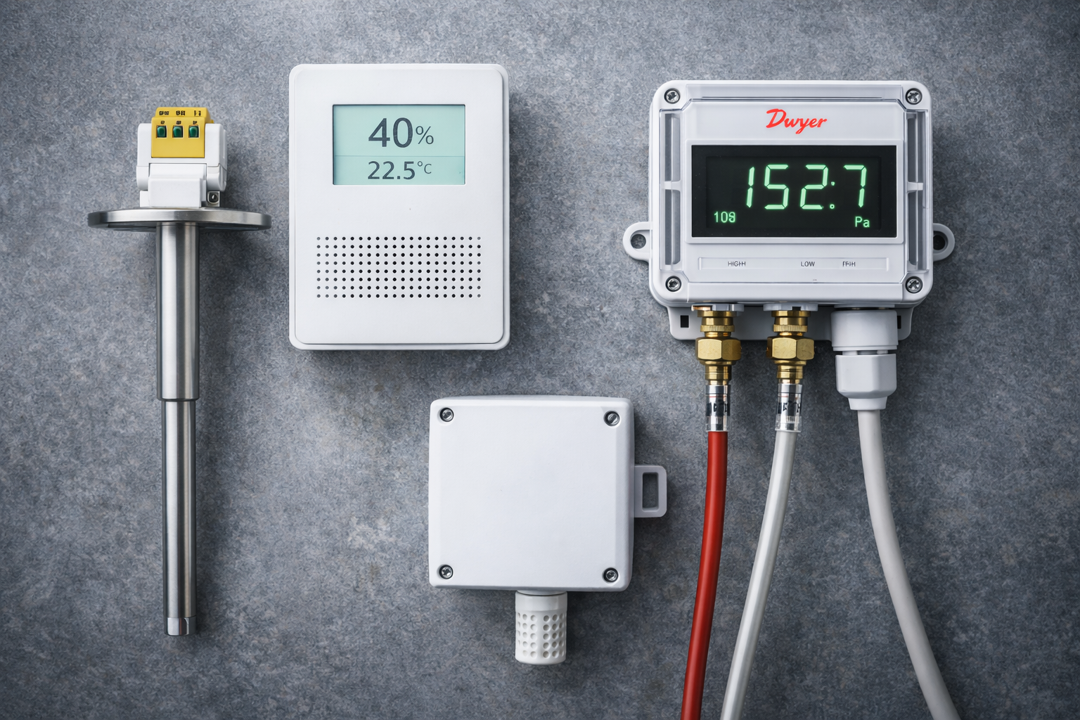
In any Building Management System (BMS), the controller acts as the brain, but the sensors serve as the vital nervous system. Regardless of how advanced your digital controls are, they cannot maintain occupant comfort or optimize energy efficiency if they receive inaccurate data from the field.
At Controls Traders, based in Adelaide, South Australia, we have over 40 years of industry experience supplying high-quality Sensors & Transducers. To help facility managers and HVAC technicians navigate system upgrades, here is our technical breakdown of the most common HVAC sensor types and their applications.
1. Temperature Sensors
Temperature sensors are the primary variable for roughly 90% of HVAC control loops. Most standard BMS applications utilize Thermistors (such as 10k Type 2 or 10k Type 3), which are cost-effective and highly sensitive to temperature changes. For critical process control, central plant supplies, or thermal energy calculation, RTDs (like PT100 or PT1000) are used because they offer extreme stability and linear accuracy.
Depending on where you are measuring the temperature, you will need a specific form factor:
- Room Sensors: These aesthetic, wall-mounted units provide fast responses to occupant loads in office VAV zones.
- Duct Sensors: Available as rigid probes for small ducts or flexible averaging elements for large AHU mixed-air plenums. Averaging sensors are critical in AHUs to prevent the BMS from reacting to isolated streaks of cold outside air.
- Pipe Sensors: Immersion sensors sit inside a stainless steel or brass thermowell directly in the water flow, providing the highly accurate readings required for chiller supplies. Strap-on variants are also available for retrofits where the system cannot be drained.
- Outside Sensors: Built with weatherproof enclosures and sun-shields to ensure solar radiation does not artificially inflate the ambient air reading.
2. Indoor Air Quality (IAQ): CO₂ and Humidity Sensors
Modern HVAC design relies heavily on Demand Control Ventilation (DCV), where outside air intake is strictly matched to building occupancy.
- CO₂ Sensors: By measuring carbon dioxide levels, these sensors tell the BMS exactly how many people are in a room. If a meeting room is empty, the BMS signals the system to reduce fresh air intake, saving significant energy on conditioning outside air. For accurate readings, CO₂ sensors must always be installed at breathing-zone height (1.2m–1.5m) and kept away from supply air diffusers.
- Humidity Sensors: Proper humidity control is critical for occupant comfort and preventing mold in commercial spaces. Today, humidity sensing is often conveniently combined with temperature and CO₂ monitoring in a single multi-function room unit, such as those manufactured by Siemens or BAPI.
3. Differential Pressure (DP) Sensors
A Differential Pressure Transducer measures the difference in pressure between two distinct points (a high side and a low side) and converts that mechanical difference into an electrical signal (like 0-10V) for the BMS.
DP sensors generally fall into two categories:
- Air DP Sensors (Dry Media): Essential for airside operations, these measure in Pascals (Pa). They are used for filter monitoring (triggering a "Dirty Filter" alarm as pressure drops across a clogged filter bank), monitoring duct static pressure to tell Variable Speed Drives (VSDs) to speed up or slow down, and ensuring safe building pressurization in stairwells.
- Liquid DP Sensors (Wet Media): These measure pressure drops across pumps, chillers, and valves, typically reading in kPa or Bar. They are crucial for maintaining proper hydraulic stability in chilled water and heating water loops.
Sourcing the Right Sensors in Australia
Using an incorrect sensor type or suffering from poor placement can lead to system "hunting," massive energy waste, and uncomfortable tenants.
If you need to replace a drifting sensor or specify parts for a new digital controls upgrade, Controls Traders stocks a comprehensive range of sensors from industry-leading brands, including BAPI, Siemens, Automated Components Inc (ACI), and Dwyer.
We warehouse our inventory locally in Adelaide, ensuring that you don't have to wait weeks for international freight. Browse our full range of Sensors & Transducers online or call our technical support team on 1300 740 140 for expert selection advice and fast, Australia-wide delivery.
Frequently Asked Questions
What is the most common type of temperature sensor used in HVAC?
The 10k Type 2 (10k-2) thermistor is the most widely used temperature sensor in commercial HVAC and BMS applications. It is cost-effective, highly sensitive, and natively supported by almost every major DDC controller brand including iSMA, Siemens, Schneider, and EasyIO. Controls Traders stocks a full range of 10k-2 sensors from BAPI and ACI for same-day dispatch from Adelaide.
What is the difference between a thermistor and an RTD?
A thermistor (like the 10k-2) is highly sensitive and inexpensive, making it ideal for standard zone control in offices and AHUs. An RTD (Resistance Temperature Detector), such as a PT100 or PT1000, is more accurate and stable across a wide temperature range, making it better suited for critical applications like chiller supply monitoring or thermal energy metering. RTDs cost more but are essential where precise measurement is non-negotiable.
Where should a CO₂ sensor be installed in a room?
CO₂ sensors must be installed at breathing-zone height — between 1.2m and 1.5m above floor level — and positioned away from supply air diffusers. Placing a sensor directly under a diffuser will cause it to read artificially low CO₂ levels (because it is sampling diluted supply air), tricking the BMS into thinking the room is empty and reducing fresh air intake when it should not.
What is the difference between a room sensor and a duct sensor?
A room sensor is a wall-mounted unit that measures the ambient conditions in the occupied space — it is designed for airflow exposure and fast response to occupant heat loads. A duct sensor is a probe mounted inside the ductwork to measure supply air, return air, or mixed air temperatures. Averaging duct sensors are used in large AHU plenums where a single-point probe would not capture a representative reading across the full duct cross-section.
What causes a differential pressure sensor to give incorrect readings?
The most common causes are: incorrect port connection (high and low ports swapped), blocked or kinked pneumatic tubing, the sensor being mounted in a location exposed to vibration, or selecting a sensor with the wrong pressure range for the application. For filter monitoring, a 0–250 Pa range sensor is typically correct. For duct static pressure, a 0–500 Pa or 0–1000 Pa range is usually more appropriate depending on the system design.
Read more
BACnet vs Modbus: Which Protocol Is Best for HVAC Controls?
 In the world of Building Management Systems (BMS) and HVAC integration, reliable communication between your controllers, sensors, and actuators is the backbone of an efficient plant room. For integrators and facility managers, choosing the right open communication protocol for Direct Digital Control (DDC) units is a critical decision.
The two undisputed heavyweights in building automation are BACnet and Modbus.
While both protocols allow controllers and end devices to "talk" to one another on a network, they were designed in different eras and for different primary purposes. At Controls Traders, we supply premium hardware that speaks both languages natively, including iSMA, Siemens, and Schneider controllers.
Here is our technical guide to understanding BACnet and Modbus, and how to choose the right protocol for your next HVAC integration.
What is BACnet?
BACnet (Building Automation and Control networks) was purpose-built for the building automation industry. It is designed specifically to handle the complex, hierarchical data requirements of modern HVAC, lighting, and security systems.
In HVAC applications, you will most commonly encounter BACnet MS/TP (Master-Slave/Token-Passing), which runs on the RS-485 physical layer and connects devices in a daisy-chain topology.
- How it works: A token is passed between controllers; only the device currently holding the token is permitted to transmit data.
- The Gear: BACnet is the native language for most of the premium BMS controllers we stock, including iSMA, EasyIO, and Siemens. Furthermore, intelligent field devices like Belimo Actuators now frequently come with BACnet MS/TP built-in for seamless integration.
- The Advantages: BACnet provides real-time speed, high reliability, and a rich, object-oriented data structure that makes discovering and mapping complex network points incredibly efficient.
What is Modbus?
Modbus is the older of the two protocols, originally developed for industrial automation and Programmable Logic Controllers (PLCs). Despite its age, it remains fiercely relevant due to its simplicity, robustness, and universal acceptance.
Like BACnet, it often runs over an RS-485 serial connection (known as Modbus RTU) or over Ethernet (Modbus TCP/IP).
- How it works: Modbus uses a strict Master/Slave architecture. A single Master device requests data or sends commands, and the Slave devices (like sensors or drives) simply listen and respond.
- The Gear: Many heavy-duty industrial components, variable speed drives (VSDs), and energy meters rely heavily on Modbus RTU.
- The Advantages: It is lightweight, remarkably easy to troubleshoot, and requires very little processing power from the end devices.
Head-to-Head Comparison
When deciding which protocol to standardize on for a new site or retrofit, system integrators should consider the following differences:
1. Data Structure and Discoverability
- BACnet: Uses an "object-oriented" structure. A BACnet controller doesn't just send a raw number; it sends an object (like an Analog Input) complete with metadata, such as engineering units (°C or Pa), status flags, and descriptions. BACnet devices are also "discoverable," meaning a BMS supervisor can scan the network and automatically pull in all available points.
- Modbus: Uses a register-based structure. It transmits raw data values (e.g., a 16-bit integer). The BMS must be manually programmed with a register map provided by the manufacturer to understand that "Register 40001" equals "Supply Air Temperature."
2. Network Speed and Complexity
- BACnet: Because of token-passing and high bandwidth capabilities, BACnet is ideal for executing rapid, complex logic like PID loops across multiple devices.
- Modbus: Excellent for simple, repetitive polling of data. However, because the Master must individually poll every Slave, a network with hundreds of Modbus devices can suffer from high latency.
3. Application Focus
- BACnet: Best suited for high-level control applications—such as modulating actuators, VSDs, and coordinating complex plant room strategies.
- Modbus: Ideal for simple equipment integrations, such as reading electrical meters, basic PLCs, or polling simple field sensors.
Bridging the Gap in Modern HVAC
Fortunately, you rarely have to choose just one. Modern HVAC systems are inherently hybrid.
For instance, you might use a powerful **Siemens or iSMA** controller acting as a BACnet router to manage the high-level logic of your plant room. That same controller can utilize a secondary RS-485 port to poll a daisy-chain of Modbus RTU electrical meters, seamlessly translating that Modbus data into BACnet objects for the main BMS supervisor to read.
Even field-level devices have adapted to this dual reality. Premium hardware, such as Belimo actuators, are designed to be plug-and-play with major building management systems, offering native compatibility with BACnet, Modbus RTU, and Modbus TCP/IP straight out of the box. This ensures faster commissioning and dramatically reduces the hassle of integrating third-party controls.
Need Help Selecting Your BMS Hardware?
Whether you are pulling MS/TP cable for a network of BACnet controllers or integrating legacy Modbus RTU field devices into a new digital BMS, selecting the right hardware is essential.
Controls Traders is an Australian-owned supplier located in Stepney, Adelaide. We warehouse a massive inventory of DDC controllers, gateways, and smart actuators from globally trusted brands like Belimo, Siemens, Schneider, and Honeywell.
We offer fast, reliable delivery anywhere, Australia-wide.
Ready to upgrade your control network? Request a quote online or call our technical team today on 1300 740 140 to discuss your protocol integration needs
Read more
A Guide to HVAC Control Systems for Facility Managers

If you are managing a commercial building in Australia, you know that HVAC consumption typically accounts for 40–50% of your total electricity bill. For facility managers, ensuring that these systems run efficiently is critical for both occupant comfort and the bottom line.
A modern HVAC control system—often integrated into a broader Building Management System (BMS) or Building Automation System (BAS)—is the digital intelligence that runs your facility. It automates the flow of air and water, allowing your building to react to real-time demands rather than relying on manual adjustments.
At Controls Traders, we have over 40 years of industry experience supplying high-quality building automation controls across Australia. Whether you are looking to understand your current setup or planning an upgrade, here is your essential guide to how an HVAC control system works.
The Core Components of an HVAC Control System
An effective control system can be broken down into three main categories: the brain, the nervous system, and the muscles.
1. The Brains: Controllers and Thermostats
The controllers are the digital intelligence of your HVAC system. They receive data from the building, process it through programmed logic (like PID loops), and send commands to the mechanical equipment.
- Stand-alone Controllers: Ideal for local control of individual zones or small equipment.
- BMS Controllers: For large facilities, Direct Digital Control (DDC) units connect via open communication protocols like BACnet or Modbus. This allows all equipment to be monitored and managed from a central supervisor or touch screen. We supply highly capable controllers from brands like iSMA, Siemens, and Schneider.
2. The Nervous System: Sensors
No matter how advanced your controller is, it cannot maintain efficiency if it receives inaccurate data. Sensors measure the physical environment and feed this data back to the BMS.
- Temperature Sensors: Used in rooms, ducts, and pipes to ensure cooling and heating targets are met.
- CO₂ and Indoor Air Quality Sensors: Critical for Demand Control Ventilation (DCV). By monitoring CO₂ at the breathing zone height, the BMS knows exactly how many occupants are in a room and adjusts fresh air intake accordingly, saving energy when rooms are empty.
- Differential Pressure Sensors: These measure pressure drops across filters (triggering "dirty filter" alarms) or monitor static pressure in ducts to control fan speeds.
For a detailed breakdown of which sensor type suits which application — room vs. duct vs. immersion, thermistor vs. RTD — see our guide on choosing the right temperature sensor for your BMS.
3. The Muscles: Actuators and Valves
Once the controller makes a decision, it needs a physical mechanism to execute it. This is where Actuators and Valvescome in.
- Valve Actuators: These are electric motors that open, close, or modulate valves to control the flow of chilled or hot water through the building.
- Damper Actuators: These regulate the flow of air through ductwork and Air Handling Units (AHUs).
- Pressure-Independent Control Valves (PICVs): A major upgrade for variable flow systems, PICVs mechanically absorb pressure fluctuations to prevent over-pumping and "Low Delta T Syndrome," ensuring optimal chiller efficiency. We stock a massive range of premium actuators and valves from Belimo and Siemens.
4. The Efficiency Drivers: Variable Speed Drives (VSDs)
Older HVAC systems ran fans and pumps at 100% full speed constantly, wasting immense amounts of power. Variable Speed Drives (VSDs) act as a "dimmer switch" for your heavy motors. By slowing a fan down by just 20% to match the actual airflow demand, a VSD can reduce the fan's electricity consumption by roughly 50%.
Protecting Your Investment
Facility managers know that "uptime" is everything. Your control panels contain sensitive electronics that are highly susceptible to "dirty power" and momentary voltage sags. Integrating Industrial UPS Systems into your mechanical switchboards ensures that your BMS controllers, network hardware, and field power supplies stay online during power blips, preventing data corruption and plant room blindness.
Frequently Asked Questions (FAQs)
What is the difference between a stand-alone controller and a BMS controller? A stand-alone controller provides local control for a specific piece of equipment or zone, whereas a BMS controller integrates into a larger network (often using BACnet or Modbus) to allow centralized monitoring, logging, and remote tuning of the entire building.
How can I improve my existing HVAC energy efficiency? The fastest ways to improve efficiency are upgrading to Variable Speed Drives (VSDs) to reduce fan/pump speeds at partial loads, and installing Pressure-Independent Control Valves (PICVs) to prevent chilled water overflow. Additionally, ensuring your CO₂ sensors are correctly placed allows for intelligent Demand Control Ventilation.
Where can I buy HVAC control parts in Australia? Controls Traders is an Australian-owned business based in Stepney, South Australia. We warehouse a massive inventory of trusted global brands—including Belimo, Siemens, Schneider, and Honeywell—and offer fast delivery anywhere across Australia.
What is a Building Management System (BMS) and do I need one? A Building Management System (BMS) — also called a Building Automation System (BAS) — is a centralised software platform that connects and monitors all of your HVAC controllers, sensors, and actuators from a single interface. For buildings with multiple zones, AHUs, or chillers, a BMS is strongly recommended. It enables energy reporting, remote fault detection, scheduled setpoints, and trend logging — all of which are difficult or impossible to manage manually across multiple stand-alone controllers.
How do I know if my HVAC sensors need replacing? Common signs of a failing HVAC sensor include: rooms that are consistently over- or under-cooled despite correct setpoints, BMS alarms flagging out-of-range readings, or sensor values that do not change even when conditions clearly have. Temperature sensors can drift over time, and CO₂ sensors typically require recalibration or replacement every 5–7 years. Controls Traders stocks replacement sensors from Belimo, Siemens, and BAPI for fast Australia-wide delivery.
What is Demand Control Ventilation (DCV) and how does it save energy? Demand Control Ventilation (DCV) uses CO₂ sensors placed at breathing zone height to measure actual occupancy in a space. When CO₂ levels are low — indicating fewer occupants — the BMS reduces fresh air intake to only what is needed. This prevents over-ventilating empty rooms, which is one of the most common sources of wasted HVAC energy in commercial buildings. DCV is particularly effective in spaces with variable occupancy such as conference rooms, open-plan offices, and function centres.
What is the lifespan of an HVAC actuator? Most quality HVAC actuators from brands like Belimo and Siemens are rated for 60,000 operating cycles or more, which in a typical commercial HVAC application translates to 10–15 years of service life. Actuators in high-cycle applications — such as modulating valves on chilled water coils — may wear sooner. Signs of a failing actuator include hunting (constantly adjusting without settling), failure to reach setpoint, or a seized shaft. Controls Traders stocks a full range of direct-replacement Belimo and Siemens actuators ready for same-day dispatch from Adelaide.
Need to replace a faulty part or upgrade your facility's controls? With over 40 years of combined HVAC and automation expertise, our team is ready to help. Request a quote online or call us today on 1300 740 140

Top 5 Belimo Products for Australian HVAC Installers
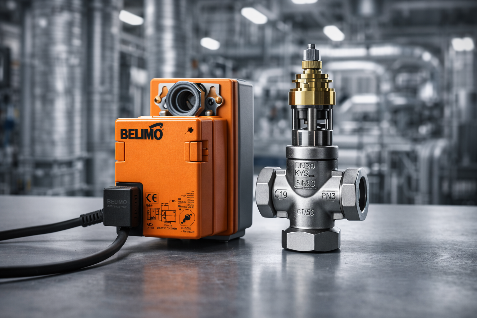
For Australian HVAC installers and facility managers, Belimo is synonymous with reliability. Whether you are fitting out a new commercial tower in Sydney or retrofitting a hospital plant room in Adelaide, you know that a Belimo orange actuator simply works.
However, the Belimo range is vast. Beyond the standard damper actuators, there are high-tech valves and safety solutions that can drastically reduce commissioning time and energy usage.
At Controls Traders, we warehouse a massive range of Belimo stock in South Australia, ready for fast delivery nationwide. Drawing on our 40 years of industry experience, here are the Top 5 Belimo products that every Australian installer should know about.
1. Belimo LF Series (Spring Return Damper Actuator)
Safety is non-negotiable in Australian building codes. The Belimo LF Series is a staple for critical applications where a fail-safe position is required during a power outage.
- Specs: 4Nm torque, Spring Return, available in 24V or 240V options.
- Typical Application: Outside air dampers, fire/smoke isolation dampers, and freeze protection strategies.
- Why Installers Love It: It provides instant mechanical fail-safe reliability. If power is cut, the spring drives the damper fully closed (or open) within seconds.
- Availability: We stock the BEL-DAM-LF series ready for dispatch.
2. Belimo NR24A-SR (Rotary Damper Actuator)
When you need precise modulation for standard air handling, the NR Series is the industry workhorse. It is robust, easy to mount, and integrates seamlessly with almost any BMS.
- Specs: 10Nm torque, 24V AC/DC, Modulating (0-10V or 4-20mA control).
- Typical Application: Regulating airflow in Air Handling Units (AHUs) and large VAV zones.
- Why Installers Love It: It features a manual override button and a universal clamp that fits easily onto existing damper jackshafts. The 10Nm torque is the "Goldilocks" size—perfect for most mid-sized commercial dampers.
3. Belimo Energy Valve™
This is the future of hydronic control. The Energy Valve is not just a valve; it is a 5-in-1 device combining a valve, actuator, flow sensor, and two temperature sensors.
- Specs: Measures Flow (L/min), Power (kW), and Energy (kWh), plus Supply/Return temperatures.
- Typical Application: Green Star rated buildings, university campuses, and sites requiring precise energy metering and "Delta T" management.
- Why Installers Love It: It solves "Low Delta T" syndrome automatically. The valve logic monitors coil performance and modulates to ensure the water absorbs heat efficiently, preventing chiller over-pumping.
4. Belimo Pressure Independent Control Valve (PICV)
In variable flow systems, pressure fluctuations can cause "ghost flows" and hunting. The Belimo PICV combines a differential pressure regulator with a control valve to maintain constant flow regardless of pressure changes.
- Specs: Dynamic balancing with tight close-off pressure. Available in various flow ranges (Kv).
- Typical Application: Fan Coil Units (FCUs) and chilled beams in multi-story office buildings.
- Why Installers Love It: It simplifies commissioning. You don't need to balance the system iteratively; you just set the maximum flow dial on the valve, and the internal regulator handles the rest.
5. Belimo Characterised Control Valve (CCV)
Standard ball valves often have poor flow characteristics (a small opening lets through too much water). Belimo CCVs feature a specialized disc inside the ball port that ensures an "equal percentage" flow curve.
- Specs: High close-off pressure, zero leakage, and a self-cleaning ball design.
- Typical Application: Heating and cooling coils where precise temperature stability is required.
- Why Installers Love It: They eliminate the "hunting" common with cheap ball valves. The precise control disc ensures that a 10% opening equals 10% thermal output, making PID loop tuning much easier for the controls technician.
Summary
Whether you need the basic reliability of an NR24A-SR damper actuator or the advanced data analytics of an Energy Valve, choosing Belimo ensures you aren't returning to the site to replace failed gear in six months.
At Controls Traders, we are an Australian-owned business with deep stock levels of Belimo Actuators and valves in our Adelaide warehouse. We understand the local market and can help you cross-reference old part numbers to find the modern Belimo equivalent.
Read more
Where to Buy HVAC Differential Pressure Sensors in Australia
For HVAC installers and commissioning technicians, the differential pressure (DP) sensor is a critical component. Whether you are proving flow on a chiller or maintaining static pressure in a duct, you cannot commission a building without accurate pressure readings.
Finding these sensors in stock locally, however, can be a challenge. Waiting three weeks for a sensor to arrive from overseas often isn't an option when you have a handover deadline looming.
At Controls Traders, we warehouse a comprehensive range of [Differential Pressure Sensors] in Adelaide, ready for immediate dispatch across Australia. Here is what you need to know before you buy.
1. What Differential Pressure Sensors Do
A differential pressure sensor measures the difference in pressure between two points in a system—the high side and the low side. It converts this mechanical difference into an electrical signal (typically 0-10V or 4-20mA) that your Building Management System (BMS) can read and act upon.
In modern HVAC, these sensors are the "eyes" of the system, allowing the BMS to modulate fans and pumps to match actual building demand rather than guessing.
2. Types and Ranges
When sourcing a sensor, you generally need to choose between two main categories:
- Air Differential Pressure (Dry Media): Used for measuring air pressure in ducts, plenums, and room spaces. These typically measure in Pascals (Pa).
- Liquid Differential Pressure (Wet Media): Used for measuring pressure drop across pumps, chillers, and valves. These are measured in kPa or Bar.
We stock brands like Dwyer, BAPI, ACI, and Siemens that offer field-selectable ranges. This means you can buy one sensor and configure it for 0-250Pa or 0-500Pa on-site, saving you from carrying multiple part numbers in your van.
3. Applications in HVAC
You will typically install these sensors for three main applications:
- Filter Monitoring: Measuring the pressure drop across a filter bank. As the filter clogs, pressure rises, triggering a "Dirty Filter" alarm in the BMS.
- Duct Static Pressure: Located two-thirds down the duct, this sensor tells the VSD on the supply fan to speed up or slow down to maintain constant airflow as VAV boxes open and close.
- Building Pressurization: Critical for stairwell pressurization systems (fire safety) to ensure smoke does not enter escape routes.
4. Key Buying Considerations
Before placing an order, check these three specs:
- Output Signal: Does your controller require 0-10V, 4-20mA, or a direct BACnet/Modbus connection?.
- Display: Do you need an LCD screen on the unit for local maintenance checks?
- Unidirectional vs. Bidirectional: Are you measuring positive pressure only (0 to 100Pa) or do you need to monitor positive and negative swings (-50 to +50Pa)?
5. Why Local Stock Matters
Supply chain delays are the enemy of profitable projects. Many suppliers list items online that are actually drop-shipped from Europe or the US, leading to unexpected delays.
At Controls Traders, we warehouse our stock locally in South Australia. This "convenience factor" means you don't have to wait for international freight. If a sensor fails on a critical site, you need a replacement in days, not weeks.
6. Where to Buy in Australia
You can purchase high-quality sensors directly from Controls Traders. We are an Australian-owned business based in Stepney, South Australia.
- Brands We Stock: We carry trusted global names including Dwyer, Belimo, Siemens, BAPI, Veris, and Automated Components Inc (ACI).
- Delivery: We offer global shipping and fast delivery Australia-wide.
- Support: With over 40 years of industry experience, our team can help you cross-reference old part numbers to find a modern equivalent that fits your budget.
7. Summary
Don't let a missing sensor hold up practical completion. Whether you need a simple switch for a filter or a high-precision transducer for a lab, buying from a local supplier ensures you get the right part, right now.
Read more