


Differential Pressure Sensors for HVAC: A Technical Selection Guide
Differential pressure (DP) measurement is fundamental to HVAC system operation. Whenever air or fluid passes through a restriction — a filter bank, a coil, a duct fan — there is a pressure difference across it. Differential pressure sensors measure that difference and convert it to a signal a BMS or controller can act on. The sensor class covers an enormous range of applications: from detecting a 5 Pa pressure differential across a door gap in a hospital isolation room, to monitoring the 1,000+ Pa pressure rise across a supply air fan. Selecting the wrong sensor — one with a range that is too wide, or an output that does not match the BMS analogue input — results in poor measurement resolution, unnecessary field rework, or incorrect alarm set points.
This guide covers the operating principles behind DP sensors, the pressure ranges and output signal types available, and a step-by-step selection process applicable to the most common HVAC applications. It references products available through Controls Traders, including the BAPI differential pressure sensor range, which covers room pressurisation through to high-pressure industrial air handling. For a broader overview of HVAC sensors available from Controls Traders, including temperature, humidity, and CO₂ types, visit the sensors category page.
How Differential Pressure Sensors Work
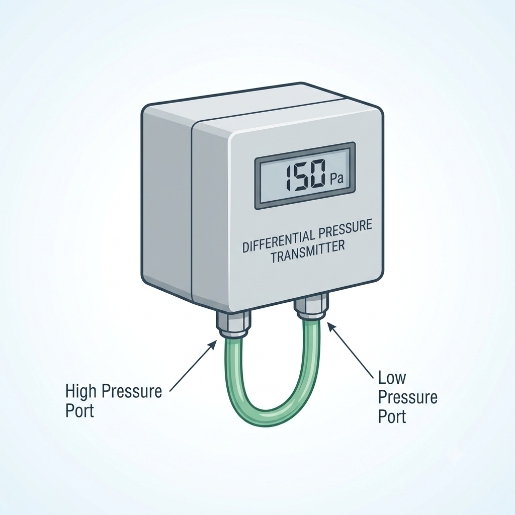
A differential pressure sensor has two pressure ports — a high-pressure port and a low-pressure port — each connected to the measurement point via tubing or direct-mount fittings. The sensor measures the pressure at each port and outputs a signal proportional to the difference between them. When both ports are at equal pressure (the reference condition), the output represents zero differential pressure. When the high-pressure port is at greater pressure than the low-pressure port, the output increases proportionally.
Three primary sensing element technologies are used in HVAC-grade DP sensors:
- Piezoresistive silicon diaphragm — the most common technology in HVAC differential pressure sensing. Differential pressure deflects a silicon diaphragm; the resulting strain changes the resistance of doped silicon elements arranged in a Wheatstone bridge circuit. The bridge imbalance is amplified and conditioned to produce the output signal. This technology is robust, accurate to ±2% of full scale in HVAC-grade instruments, and well-suited to both air and water applications.
- Capacitive sensing — differential pressure deflects a diaphragm, changing the capacitance between two plates on either side of it. Capacitive sensors offer excellent resolution and are preferred for ultra-low pressure ranges below 25 Pa, where the diaphragm deflection is very small and a capacitance measurement is more sensitive than a resistance measurement. This technology is the standard choice for hospital room pressurisation applications.
- Variable reluctance — a mechanical diaphragm changes the reluctance of a magnetic circuit. Less common in modern HVAC applications, this technology appears in some legacy and industrial transmitters. It is more robust against overrange events but is rarely specified in new HVAC installations.
Signal conditioning electronics convert the raw sensor element output to a standard electrical signal — 4–20 mA, 0–10 V, or a digital protocol such as BACnet MS/TP or Modbus RTU. Accuracy of ±2% of full scale is typical for standard HVAC-grade instruments; high-accuracy process transmitters achieve ±0.25% of full scale but are rarely required in building HVAC applications.
Pressure Ranges and HVAC Applications
The pressure range of a DP sensor determines both its measurement ceiling and its resolution. A sensor with a 0–6,250 Pa range used on a 25 Pa room pressurisation application will produce only 0.4% of its full output at the target set point — effectively unusable for control. Matching the sensor range to the application is critical.
| Range Category | Pressure Range (Pa) | Typical HVAC Application |
|---|---|---|
| Ultra-low | <25 Pa | Hospital isolation room pressurisation, clean room pressure monitoring |
| Low | 25–125 Pa | Filter monitoring in low-velocity systems, pharmaceutical clean room pressure |
| Medium | 125–1,250 Pa | VAV box airflow measurement, supply duct static pressure, AHU filter banks, fan monitoring |
| High | 1,250–6,250 Pa | High-velocity ducted systems, industrial air handling units |
| Bidirectional | ±12.5 to ±250 Pa | Room pressurisation where differential direction may reverse |
The bidirectional range category deserves specific attention for room pressurisation applications. A unidirectional sensor (0 to +X Pa) can only report pressure in one direction. If the controlled space momentarily goes negative relative to the reference — which can occur during door opening, a supply fan trip, or poor initial commissioning — a unidirectional sensor will either read zero or saturate at its lower limit. It cannot communicate to the building automation system that the pressure has reversed. A bidirectional sensor (±X Pa) produces an output above mid-scale for positive pressure and below mid-scale for negative pressure, allowing the BMS to detect and respond to pressure reversals.
Key HVAC Applications
Filter Monitoring
Filter monitoring is the most common DP sensor application in commercial HVAC. A sensor is installed across the filter bank — high-pressure port upstream, low-pressure port downstream — and the output is monitored by the BMS. As filters accumulate dust and particulate, the pressure drop across the bank increases from the clean filter resistance toward the final resistance at which the filter should be changed.
ASHRAE recommends DP-based filter monitoring rather than time-based scheduling because identical filters in different systems — one handling clean office air, another handling dusty warehouse return air — will reach their final resistance at very different rates. Time-based replacement wastes filters that still have useful life, or leaves loaded filters in service beyond their design change point.
For MERV 8–13 filters at typical AHU face velocities of 2–3 m/s, initial resistance ranges from 40–80 Pa and final resistance (the filter change alarm point) is typically 150–250 Pa. Select a sensor with a range approximately 20% above the expected final resistance. A 0–250 Pa sensor is appropriate for many commercial HVAC filter banks; a 0–500 Pa sensor provides additional headroom for higher face velocity applications.
VAV Box Airflow Measurement
VAV box airflow measurement uses a DP sensor paired with a Pitot tube, flow cross, or factory-fitted flow station inside the VAV terminal unit. The flow element creates a measurable velocity pressure differential by separating total pressure (measured at the upstream stagnation point) from static pressure. The VAV controller derives volumetric airflow using the Bernoulli relationship: V = √(2ΔP/ρ), where V is velocity (m/s), ΔP is velocity pressure (Pa), and ρ is air density (approximately 1.2 kg/m³ at standard conditions). Volumetric flow is then calculated by multiplying velocity by the known duct cross-section area.
Typical velocity pressure at an airflow of 5 m/s in a 300 mm round duct is approximately 15 Pa. At minimum design airflow — often 30–40% of maximum — velocity pressure drops to approximately 1.5–2.5 Pa, placing demanding resolution requirements on the sensor. Select a sensor with a range of 0–125 Pa to cover the full VAV operating range, and confirm that the sensor's resolution is adequate at the minimum flow condition.
Building Pressurisation
Building pressurisation control is a critical function in hospitals, clean rooms, pharmaceutical laboratories, and isolation rooms. Controlled pressure differentials prevent cross-contamination between spaces: positive pressure rooms (+12.5 Pa relative to adjacent corridor) push air outward, preventing particulates from entering; negative pressure rooms (−12.5 Pa) draw air inward, preventing airborne contaminants from escaping. These requirements are governed by AS 1668 and the National Construction Code (NCC/BCA) for healthcare facilities.
Sensors for this application must be bidirectional with adequate resolution at the set point. A ±25 Pa bidirectional sensor is appropriate for a ±12.5 Pa target. Resolution of 0.1 Pa or better is required to support tight pressure control within ±1–2 Pa of set point. Mount the sensor in a location with stable temperature — avoid direct exposure to supply air diffusers or locations subject to temperature swings that cause zero drift. Reference the low-pressure port to a location representative of corridor or adjacent space pressure, not immediately adjacent to a supply diffuser or door gap.
Fan and AHU Performance Monitoring
AHU performance monitoring uses DP measurement across the complete air handling unit — from inlet plenum to supply fan outlet — or across individual components such as cooling coils and heating coils. The DP baseline is established at commissioning and stored in the BMS. Deviation from the baseline indicates component fouling: a rising DP across a cooling coil indicates biofilm or scale accumulation; a rising DP across the complete AHU may indicate a combination of filter loading and coil fouling. DP-based AHU monitoring allows maintenance to be targeted to actual condition rather than calendar schedules.
Sensor vs. Transmitter — Terminology
The terms DP sensor and DP transmitter are used interchangeably throughout HVAC specifications and product catalogues. Technically, a sensor refers to the detecting element — the silicon diaphragm, capacitive cell, or mechanical element that responds to pressure. A transmitter includes signal conditioning circuitry and a standard electrical output that can be connected directly to a BMS analogue input. In HVAC practice, when a project specification calls for a "DP sensor, 0–250 Pa, 4–20 mA output," it is invariably referring to a complete transmitter. The technical distinction matters only when sourcing replacement detecting elements for an existing transmitter, or when specifying a field-mount transmitter to be connected to a remote sensing element.
Output Signal Options
Three output signal types are common in HVAC DP sensors:
- 4–20 mA (two-wire, loop-powered) — the most common output for HVAC BMS analogue inputs. A current-based signal is immune to voltage drop caused by cable resistance, making it suitable for long cable runs. The 4 mA live-zero is a significant reliability advantage: the BMS can distinguish between a zero-pressure reading (output at 4 mA) and a broken cable or failed sensor (output below 4 mA). Use 4–20 mA for cable runs exceeding 30 metres, or wherever signal cables share conduit with power wiring. Requires a 24 VDC supply at the BMS analogue input card.
- 0–10 V (three-wire) — simpler wiring at the sensor, with three conductors: supply positive, signal, and common. The 0 V zero is a disadvantage in fault detection — a broken wire reads the same as a zero-pressure reading. Susceptible to voltage drop on long cable runs; 4–20 mA is preferred for runs beyond 30 metres.
- Digital (BACnet MS/TP, Modbus RTU) — digital output sensors are increasingly common in modern HVAC installations. Advantages include multiple measured values in a single device (DP, temperature, and calculated volumetric flow), direct BMS integration without consuming analogue input cards, and engineering units embedded in the protocol. For guidance on BMS protocol selection, refer to the Controls Traders article on BACnet vs Modbus. Digital sensor commissioning requires bus address configuration and is more complex than analogue wiring, but the reduction in analogue input count can offset this effort on large projects.
Step-by-Step Selection Guide
- Determine required pressure range: calculate the maximum expected process pressure for the application (maximum filter final resistance, maximum fan static pressure, or maximum room pressurisation offset). Add a 20% margin, then round up to the nearest standard sensor range.
- Select output type: confirm the BMS analogue input type (4–20 mA or 0–10 V). Choose 4–20 mA for cable runs exceeding 30 metres or where the signal cable shares a conduit with power wiring. Choose 0–10 V for short runs where wiring simplicity is the priority.
- Choose mounting type: duct-mount (sensor body mounted directly in the duct wall, pressure ports penetrating the duct), remote-mount (sensor installed in an accessible location with polyethylene tubing running to the measurement points in the duct), or panel-mount (for MCC or control panel installation on pressurised duct systems).
- Specify process connections: barbed fittings for 6 mm polyethylene tubing are standard for most HVAC duct and air-side applications. NPT threaded ports are specified for higher-pressure water and steam applications where tubing compression fittings are appropriate.
- Confirm IP rating: IP54 is the minimum for duct-mounted sensors or sensors exposed to mechanical room conditions. IP65 or higher is required for sensors in wet areas or where water hosing is possible during cleaning.
- Check auto-zero feature: some sensors perform an automatic zero calibration at power-up, sampling the output with both pressure ports vented to atmosphere before entering normal operation. This is particularly valuable where the sensor is mounted near vibration sources — fans, pumps, compressors — that could induce zero drift over time.
BAPI Differential Pressure Sensors
BAPI (Building Automation Products Inc.) manufactures a comprehensive range of differential pressure sensors calibrated specifically for HVAC applications, available in Australia through Controls Traders' BAPI product range. BAPI sensors are designed for stable performance in the variable temperature and humidity conditions typical of mechanical rooms and duct interiors, where ambient conditions can fluctuate significantly over daily and seasonal cycles.
The BAPI DP sensor range covers ±12.5 Pa bidirectional sensors for hospital room pressurisation, through standard ranges of 0–125 Pa, 0–250 Pa, 0–500 Pa, 0–1,250 Pa, and 0–6,250 Pa for filter monitoring, VAV airflow, duct static pressure, and high-pressure industrial applications. Output options include 4–20 mA, 0–5 V, 0–10 V, and BACnet MS/TP digital output. The digital output models provide simultaneous DP and temperature measurements on the same device, reducing the analogue input count on BMS panels. BAPI sensors can be specified with field-adjustable ranges and zero suppression, allowing a single stocked model to serve multiple site pressure ranges.
For selection assistance — particularly for room pressurisation applications where sensor resolution and mounting location require careful consideration — contact Controls Traders. The Controls Traders technical team can confirm sensor selection against project specifications and advise on site-specific installation requirements.
Frequently Asked Questions
What pressure range do I need for filter monitoring?
For MERV 8–13 filters at typical AHU face velocities of 2–3 m/s, initial resistance is 40–80 Pa and final resistance (filter change point) is 150–250 Pa. Select a sensor rated 0–250 Pa or 0–500 Pa so the output does not saturate before the filter reaches its change point. Add a 20% range margin above the highest expected pressure to provide headroom for variations in face velocity and filter loading rate across different operating conditions.
Can a DP sensor measure airflow in a duct?
Yes, when paired with a Pitot tube, flow cross, or flow station that creates a measurable velocity pressure differential. The DP sensor measures the difference between total pressure (stagnation) and static pressure, which is equal to velocity pressure at that point. The VAV controller or BMS then applies V = √(2ΔP/ρ) and the duct cross-section area to calculate volumetric flow in m³/s or L/s. Sensor resolution at minimum flow conditions is the critical selection parameter for this application.
What is the difference between a DP sensor and a DP transmitter?
In HVAC practice, the terms are used interchangeably. Technically, a sensor refers to the detecting element — the silicon diaphragm or capacitive cell — while a transmitter includes signal conditioning circuitry and a standard electrical output (4–20 mA, 0–10 V, or digital). When a specification calls for a "DP sensor, 4–20 mA output," it means a complete transmitter. The distinction is relevant only when sourcing replacement detecting elements for an existing transmitter housing, or when specifying a separate sensing element and signal conditioner for a specialised installation.
Should I use 4–20 mA or 0–10 V output for my BMS?
Use 4–20 mA for any cable run longer than 30 metres, or where the signal cable shares a conduit with power wiring. A current signal is not affected by cable resistance or induced voltage noise, and the 4 mA live-zero means a broken wire can be detected — the BMS input reads below 4 mA rather than zero, allowing a wiring fault to be distinguished from a genuine zero-pressure reading. Use 0–10 V where cable runs are short and wiring simplicity is the priority, noting that a broken wire will be indistinguishable from a zero-pressure reading.
How do I select a DP sensor for room pressurisation in a hospital?
Select a bidirectional sensor covering the expected range with margin — for a ±12.5 Pa target, a ±25 Pa bidirectional sensor is appropriate. Confirm the sensor resolution is 0.1 Pa or better, since tight pressure control within ±1–2 Pa of set point requires the sensor to detect small deviations reliably. Mount the sensor body in a stable environment away from supply air diffusers and direct airflow, and reference the low-pressure port to a location representative of the adjacent corridor or space pressure, not immediately adjacent to a door gap or supply diffuser.
Leave a comment
Popular Posts

Spring-Return vs Non-Spring-Return Actuators: Which Do You Need?

BAPI CO2, Humidity and Temperature Sensors: A Product and Selection Guide

Damper Actuators for AHUs and VAV Systems: Selection and Sizing Guide
