


CO₂ Sensors for Demand-Controlled Ventilation: A Technical Guide
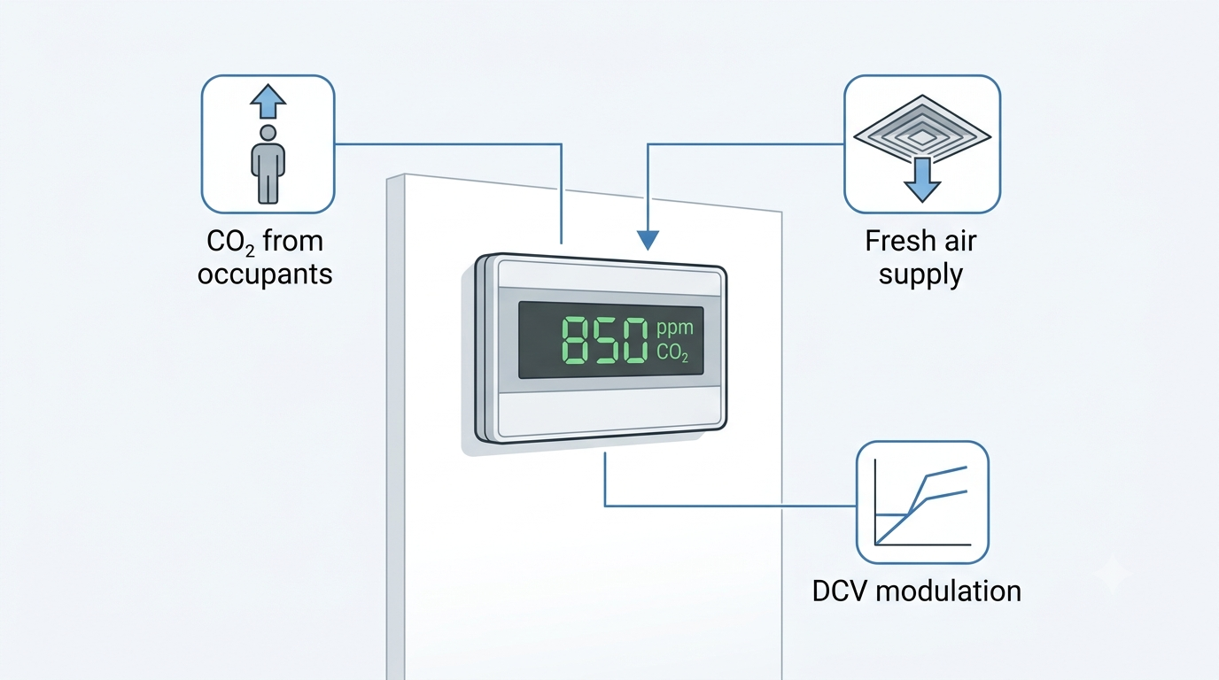
Ventilation systems sized for peak occupancy deliver far more outdoor air than necessary during periods of low or variable occupancy. A conference room designed for 40 people receiving full design airflow when only four people are present wastes substantial energy — the HVAC system overconditions outdoor air for no occupant benefit. Demand-controlled ventilation (DCV) addresses this by using CO₂ concentration as a proxy for occupancy, increasing outdoor air supply when CO₂ rises above a setpoint and reducing it when the space empties. CO₂ sensors are the measurement backbone of any DCV system. This guide covers sensor technology, placement strategies, calibration, output options, and selection criteria relevant to Australian commercial HVAC practice.
DCV is recognised in AS 1668.2 (the Australian Standard for mechanical ventilation in buildings) and is supported under the National Construction Code (NCC) as a strategy for achieving required minimum outdoor air rates while reducing energy consumption during variable occupancy. In practice, correctly commissioned DCV systems consistently deliver measurable reductions in both fan energy and conditioning load — provided the CO₂ sensors are correctly selected, placed, and maintained.
Why CO₂ as a Ventilation Indicator?
CO₂ is produced by human respiration at a rate of approximately 0.3 L/min per person at rest, rising with physical activity. Outdoor air contains approximately 420 ppm CO₂ as of the current 2024 baseline — elevated slightly from the 400 ppm figure used in older references. As occupancy increases in an enclosed space, CO₂ concentration rises above that ambient baseline. The rate of rise depends on the number of occupants, their metabolic rate, the volume of the space, and the outdoor air supply rate.
ASHRAE 62.1-2022 acknowledges CO₂ monitoring as a method for demand-controlled ventilation. A setpoint of 1,000 ppm is widely used as the upper threshold — representing the approximate equilibrium CO₂ level when ventilation is provided at the ASHRAE 62.1 person-based rate for typical office occupancy. The differential between the 420 ppm outdoor baseline and the 1,000 ppm upper setpoint provides approximately 580 ppm of working range for proportional control. An important qualification: CO₂ is an indicator of occupancy and metabolic load, not a direct measure of all indoor air quality parameters. It does not indicate elevated VOC, formaldehyde, particulate matter, or humidity. DCV based on CO₂ is appropriate for spaces where occupant-generated CO₂ is the primary driver of ventilation need — offices, conference rooms, classrooms, auditoriums, and gymnasiums. It is not appropriate as a standalone ventilation control strategy in kitchens, laboratories, car parks, or spaces with significant non-occupant-related pollutant sources.
NDIR Sensing Technology
Non-Dispersive Infrared (NDIR) is the standard CO₂ sensing technology in all HVAC-grade sensors. Alternative technologies — including electrochemical cells and metal oxide semiconductor (MOS) sensors — are occasionally found in low-cost consumer devices but are not appropriate for commercial HVAC DCV applications due to poor long-term stability, cross-sensitivity to other gases, and limited service life.
The NDIR operating principle involves four components:
- An infrared light source emits a broadband IR signal through a sealed sample chamber through which the measured air continuously flows.
- CO₂ molecules absorb IR radiation at a specific wavelength of 4.26 μm. The greater the CO₂ concentration, the greater the IR absorption at that wavelength.
- A reference wavelength — one not absorbed by CO₂ — is measured simultaneously via a second detector channel. The ratio of absorbed to reference signal is converted to a CO₂ concentration reading in ppm, compensating for any gradual degradation of the IR source.
- Signal conditioning circuitry applies temperature compensation and outputs a calibrated reading via the sensor's analogue or digital output.
NDIR has three significant advantages for HVAC applications: accuracy of ±50 ppm at calibration is readily achievable; the NDIR optical cell has no chemical reaction and does not deplete over time, giving service lives of 10–15 years; and the technology is stable across the humidity and temperature ranges encountered in occupied building environments.
Automatic Baseline Calibration (ABC)
Most HVAC CO₂ sensors use Automatic Baseline Calibration (ABC), sometimes labelled as self-calibration or background calibration. The ABC algorithm assumes that at some point during a regular cycle — typically 7–14 days — the monitored space will be unoccupied and the sensor will be exposed to outdoor air at near-ambient CO₂ concentration. Over each cycle, the algorithm records the minimum CO₂ reading and, after several cycles, uses a statistical average of those minima to reset the sensor's zero baseline.
ABC is effective and low-maintenance for the overwhelming majority of commercial HVAC applications — offices, schools, retail, conference facilities — where spaces are reliably unoccupied overnight and on weekends. The algorithm typically maintains calibration within ±50 ppm across the sensor's service life in these conditions.
ABC fails in continuously occupied spaces such as certain hospital wards, 24-hour call centres, some manufacturing and data centre environments, and other facilities that are never genuinely unoccupied. In these applications, commission sensors with manual calibration capability and calibrate against a known reference gas — 400 ppm reference gas in nitrogen is the standard for zero calibration. Alternatively, relocate the sensor to an adjacent space that is genuinely unoccupied overnight for its calibration cycle. Schedule annual manual verification in any application where there is uncertainty about whether the space achieves full unoccupied periods.
Sensor Placement — Wall (Zone) vs. Duct Return
Two primary mounting strategies are used in DCV systems, each with distinct advantages depending on the system architecture.
Wall (zone) sensors are mounted in the occupied space at breathing height — 1.2–1.5 m above finished floor level. They directly measure the CO₂ concentration in the zone being controlled, providing the highest accuracy for individual zone DCV. Wall sensors are best practice for single VAV box control, individual room DCV, and any application where occupancy varies substantially between adjacent zones. Multiple zone sensors are required in multi-zone systems — one per independently controlled zone. Common placement errors to avoid: proximity to supply air diffusers (dilution effect will cause the sensor to underread), proximity to operable windows or doors (infiltration from corridors or outdoors will depress the reading), and proximity to return air grilles (elevated local CO₂ adjacent to the grille is not representative of the zone average).
Duct return sensors are mounted in the return air duct serving the air handling unit (AHU), or in the AHU return air section itself. They measure a blended CO₂ concentration representing all zones returning air to that AHU. A single duct sensor per AHU replaces the need for individual zone sensors and can be used to control the AHU's outdoor air damper directly. The trade-off is accuracy: the mixed-air reading averages occupancy across all zones, so a high-occupancy conference room returning air to the same AHU as an empty office will have its occupancy signal diluted. Duct return sensors are most appropriate for large open-plan areas with relatively uniform occupancy distribution — not for buildings with a mix of high and low occupancy rooms on the same AHU.
| Placement Option | Best Use Case | Measurement Accuracy | Installation Complexity |
|---|---|---|---|
| Wall (zone) sensor | Single zone or individual room control | Highest — direct zone measurement | Higher (one sensor per controlled zone) |
| Duct return sensor | Central AHU serving uniform occupancy | Lower — averaged mixed-air reading | Lower (one sensor per AHU) |
| Zone + duct combination | Large buildings with mixed space types | Comprehensive | Highest cost and complexity |
DCV Setpoints and Control Logic
A proportional DCV control strategy using CO₂ as the process variable is straightforward to implement in any BMS capable of reading an analogue input. The following setpoints are typical for Australian commercial office applications under AS 1668.2 design criteria:
- Below 700 ppm: Maintain minimum outdoor air rate — typically 10 L/s per person (or the area-based minimum) per AS 1668.2 for office occupancy. The outdoor air damper holds at the minimum position.
- 700–1,000 ppm: Modulate the outdoor air damper proportionally from minimum to design (maximum) outdoor air rate as CO₂ rises through this range.
- Above 1,000 ppm: Hold outdoor air damper at maximum outdoor air rate. Investigate if CO₂ remains elevated for extended periods despite maximum ventilation — this may indicate sensor fault, unusual occupancy, or inadequate design outdoor air rate.
- Above 1,500 ppm (alarm): Generate a BMS alarm for operator investigation. Sustained readings above 1,500 ppm in a well-ventilated commercial space indicate either sensor malfunction, blocked outdoor air intake, or occupancy significantly exceeding the design assumption.
The CO₂ sensor output — typically 4-20 mA or 0-10 V scaled to 0–2,000 ppm — is wired to a BMS analogue input. The BMS modulates the outdoor air damper actuator using a PID control loop with CO₂ concentration as the process variable and outdoor air damper position as the control output. Wind-up protection and minimum position overrides are important configuration considerations: the outdoor air damper must never close below the hygienic minimum regardless of CO₂ level, and the control loop must be tuned to the relatively slow time constant of zone CO₂ response (typically 5–20 minutes for a well-mixed office zone).
The energy benefit of DCV is most pronounced in spaces with highly variable occupancy. Conference rooms, auditoriums, lecture theatres, and gymnasium spaces are frequently designed for peak occupancy loads that are achieved only a fraction of the time. DCV in these spaces can reduce HVAC energy consumption by 15–30% compared to constant-volume outdoor air systems, with the majority of savings occurring in the conditioning energy required to treat outdoor air (cooling, dehumidification, or heating depending on climate and season).
Output Signal and BMS Integration
CO₂ sensor output type must match the BMS or controller input available at the installation. Three output formats are in common use in Australian commercial BAS practice:
- 4-20 mA analogue: Scaled to 0–2,000 ppm or 0–5,000 ppm. The 4 mA lower-range value allows the BMS to detect an open-circuit fault (a 0 mA signal indicates wiring failure, not zero CO₂). Preferred for longer cable runs where voltage drop would affect a 0-10 V signal. Maximum practical run length with 4-20 mA is typically 300 m with standard 0.75 mm² cable.
- 0-10 V analogue: Scaled to the same ppm ranges. Simpler wiring (two-conductor, no loop current to maintain), but susceptible to voltage drop on long runs and to noise pickup in electrically noisy environments. Suitable for runs up to approximately 30–50 m in well-screened cable.
- BACnet MS/TP: Digital RS-485 communication. CO₂ concentration is presented as a BACnet Analogue Input object with engineering units (ppm), valid range, and fault status accessible as standard BACnet properties. Preferred where the BMS has available MS/TP field bus capacity, as it eliminates analogue input wiring, provides richer diagnostic data, and supports combination sensors delivering multiple parameters over a single two-wire connection. See our guide on BACnet vs Modbus (anticipated — verify URL before publishing) for protocol selection guidance.
- Modbus RTU: Common in sensors that also measure temperature and humidity, enabling all three measurements to be transmitted over a single screened twisted-pair bus.
Sensor Accuracy and Drift
Specifying CO₂ sensor accuracy correctly requires understanding both the initial calibration accuracy and the long-term drift behaviour. Typical HVAC-grade NDIR CO₂ sensor specifications are:
| Parameter | Typical Specification |
|---|---|
| Measurement range | 0–2,000 ppm (HVAC DCV) or 0–5,000 ppm (industrial / safety monitoring) |
| Accuracy at calibration | ±50 ppm ± 3% of reading (e.g., ±80 ppm at 1,000 ppm reading) |
| Long-term drift (with ABC) | <20 ppm per year, corrected by ABC algorithm |
| Temperature compensation range | 0–50°C (automatic); some models to 60°C for duct applications |
| Operating humidity | 0–95% RH, non-condensing |
| Rated service life | 10–15 years (NDIR optical cell) |
Temperature compensation is particularly important for duct-mount sensors, where the air temperature may differ substantially from the ambient room temperature, and where rapid airflow can affect the thermal equilibrium of the sensor cell. Verify that the sensor's stated temperature compensation range covers the expected duct temperature at the installation point — in mixed-air duct sections in Australian climates, temperatures between 10°C and 40°C are common depending on season and system configuration.
CO₂ Sensors from BAPI — Available Through Controls Traders
BAPI (Building Automation Products Inc.) offers a comprehensive range of wall-mount and duct-mount CO₂ sensors for HVAC DCV applications, available in Australia through Controls Traders. The BAPI CO₂ sensor range includes standalone CO₂ units for straightforward DCV applications as well as combination sensors integrating CO₂ with relative humidity and temperature measurement in a single housing — an arrangement that reduces wiring and installation time significantly where all three parameters are required in a zone.
BAPI CO₂ sensors support multiple output options including 4-20 mA, 0-10 V, BACnet MS/TP, and Modbus RTU, making them compatible with all major BMS platforms used in Australian commercial and industrial buildings. Combination sensors with digital outputs are particularly efficient in multi-zone systems, where a single RS-485 bus can carry CO₂, humidity, and temperature data from multiple sensors to the BMS without the wiring overhead of individual analogue inputs per parameter. For sensor selection, product availability, and technical assistance, contact the Controls Traders team.
Frequently Asked Questions
What CO₂ setpoint should I use for demand-controlled ventilation?
1,000 ppm is the widely used upper setpoint, based on ASHRAE 62.1 guidance and representing approximately the equilibrium CO₂ level when ventilation is provided at the standard person-based rate for office occupancy. A proportional control band of 700–1,000 ppm is common, where the outdoor air damper modulates from minimum to maximum outdoor air as CO₂ rises through this range. Some projects specify tighter setpoints — 800–850 ppm upper limit — where higher indoor air quality targets are required. Confirm the setpoint strategy with the project mechanical specification and the relevant authority in your jurisdiction, as NCC DtS provisions and Green Star or NABERS credits may impose specific requirements.
Do CO₂ sensors need to be calibrated regularly?
Sensors with Automatic Baseline Calibration (ABC) self-calibrate by periodically resetting their zero to the minimum reading over a 7–14 day cycle, assuming the space is unoccupied during that period. In genuinely variable-occupancy spaces, ABC typically maintains calibration within ±50 ppm over multiple years without manual intervention. For spaces that are never fully unoccupied, schedule annual manual calibration using 400 ppm reference gas. Sensors that are consistently reading more than 100 ppm above a calibrated reference despite ABC correction, or that have exceeded the manufacturer's stated service life of 10–15 years, should be replaced rather than recalibrated.
Should I mount CO₂ sensors on the wall or in the return duct?
Wall-mount (zone) sensors in the occupied space provide the most accurate reading for individual zone DCV — they measure actual occupant CO₂ without the averaging effect of mixing with air from adjacent zones. Duct-return sensors are suitable for central AHUs serving large, relatively uniform occupancy spaces, where a mixed-air reading is an acceptable proxy for zone-level CO₂ concentration. For conference rooms, classrooms, and other variable-occupancy rooms, wall-mount sensors in each room give significantly better control performance and are recommended where budget permits. A duct return sensor can still be used as a secondary check or system-level override in combination with zone sensors.
Can CO₂ sensors detect gases other than CO₂?
NDIR CO₂ sensors are designed specifically to measure CO₂ concentration by targeting the 4.26 μm absorption wavelength; they do not measure VOCs, formaldehyde, particulate matter, carbon monoxide, or other indoor air quality parameters. For spaces where multiple pollutant sources exist — commercial kitchens, laboratories, print rooms, car parks — DCV based on CO₂ alone is insufficient to ensure adequate ventilation for all contaminants. In those applications, CO₂ monitoring may still be included as part of a broader IAQ strategy, but ventilation rates must not be reduced below the level required to dilute non-occupant-generated pollutants to safe concentrations.
What is the typical service life of an NDIR CO₂ sensor?
NDIR CO₂ sensors typically carry a rated service life of 10–15 years. Unlike electrochemical sensors, which rely on a chemical reaction that gradually depletes a reagent, the NDIR optical cell operates without a consumable element — degradation occurs slowly through contamination of the optical surfaces and gradual ageing of the infrared source. Sensors that are consistently reading more than 100 ppm above a calibrated reference after ABC correction, or that have exceeded the manufacturer's stated service life, should be scheduled for replacement as part of building maintenance planning. Record sensor installation dates in the BMS or asset register to facilitate planned replacement programmes.
Leave a comment
Popular Posts

Spring-Return vs Non-Spring-Return Actuators: Which Do You Need?

BAPI CO2, Humidity and Temperature Sensors: A Product and Selection Guide

Damper Actuators for AHUs and VAV Systems: Selection and Sizing Guide
