









Our Blog
What Is Remote Temperature Monitoring? A Beginner’s Guide
Remote temperature monitoring is the use of wireless temperature sensors and advanced systems to monitor and track temperature in real-time. These systems are vital in temperature-sensitive environments, such as industrial facilities, healthcare, and logistics. They improve operational efficiency by ensuring temperatures remain within preset thresholds, protecting equipment, stock, and ensuring regulatory compliance.
To explore advanced remote monitoring solutions, you can visit Controls Traders, a trusted resource for tailored monitoring systems. By integrating temperature sensors with modern technology like IoT, businesses can easily start monitoring environments, receiving real-time alerts when temperatures rise beyond safe levels.
How Remote Temperature Monitoring Works
The process of remote temperature monitoring involves several components working together:
- Temperature Sensors: Devices that measure temperature and sometimes humidity, ensuring accuracy across a wide range. For example, wireless temperature sensors are used in server rooms and industrial setups.
- Data Transmission: Systems use Wi-Fi, cellular networks, or wireless technology to send data to centralised monitoring software.
- Monitoring Systems: Platforms analyse temperatures in real-time, trigger alarms, and send alerts when conditions deviate from preset thresholds.
By using wireless temperature monitoring systems, industries can efficiently monitor temperature-sensitive environments like storage units, production facilities, and server rooms.
Benefits of Remote Temperature Monitoring
Enhanced Safety
Remote temperature monitoring systems help maintain safe operating conditions by ensuring temperatures don’t exceed critical levels, protecting equipment and devices in various applications.
Cost Savings
These systems help save energy by optimising cooling or heating systems and preventing expensive equipment failures in temperature-sensitive environments.
Operational Efficiency
Through real-time alerts, businesses can quickly respond to anomalies, preventing downtime and ensuring compliance with industry regulations.
Versatility
With temperature monitors, industries can manage a wide range of applications, from protecting stock in logistics to maintaining optimal conditions in server rooms.
Use Cases in Industrial Settings
Manufacturing
Wireless temperature sensors ensure precise temperature control during manufacturing. For example:
- Industrial models protect materials in processes like plastic moulding or food production.
- Monitoring systems help maintain environmental stability in complex setups.
Logistics
In temperature-sensitive environments, temperature monitors and alarms protect perishables in transit. Real-time alerts signal if temperatures rise, safeguarding valuable shipments.
Healthcare
Hospitals use temperature sensors to monitor vaccine storage, ensuring compliance with regulatory requirements. Maintaining the right humidity and temperature range in critical areas prevents damage to sensitive equipment.
Key Features to Look For
When choosing a remote temperature monitoring system, consider these features:
- Wireless Technology: Ensure the system uses reliable Wi-Fi or other wireless technologies for data transmission.
- Battery Life: Long-lasting battery life ensures uninterrupted monitoring in remote locations.
- Ease of Use: Systems should be plug-and-play, requiring minimal setup.
- Integration: Compatibility with existing monitoring software improves efficiency.
- Range: A good system should cover the entire operational area, from small units to large-scale industrial models.
The Future of Remote Temperature Monitoring
Emerging technology is shaping the future of remote monitoring:
- AI-Driven Systems: Enhanced monitoring software uses AI for predictive analytics, identifying trends and preventing failures.
- Edge Computing: Enables faster analysis and response by processing data locally.
- Advanced Devices: Modern wireless temperature sensors now include additional capabilities like monitoring humidity and extending battery life.
As innovations like smart sensors and IoT-enabled devices advance, remote temperature monitoring systems will become more efficient and reliable across various applications.
Conclusion
Remote temperature monitoring systems are essential for maintaining safety, optimising operational efficiency, and ensuring regulatory compliance. By using wireless temperature sensors and advanced monitoring software, industries can protect their equipment, improve conditions in temperature-sensitive environments, and save energy. For expert solutions tailored to your needs, consult Controls Traders today.
Frequently Asked Questions
What is remote temperature monitoring used for in industrial settings?
Remote monitoring systems maintain safe temperature ranges, protecting equipment and ensuring compliance in temperature-sensitive environments.
How does a wireless remote temperature monitoring system work?
It uses sensors to collect temperature data and transmits it via Wi-Fi or cellular networks to monitoring software, which issues real-time alerts.
What are the benefits of integrating remote temperature monitoring systems with IoT?
IoT integration enhances temperature monitoring through advanced analytics, predictive maintenance, and better control of industrial models.
How do I choose the right remote temperature monitoring system for my facility?
Look for features like sensor accuracy, battery life, compatibility with existing systems, and wireless technology.
Are remote temperature monitoring systems cost-effective?
Yes, they help save energy, minimise downtime, and extend the life of equipment, making them a valuable investment.
Read more
HMI or Human Machine Interface: A Comprehensive Guide
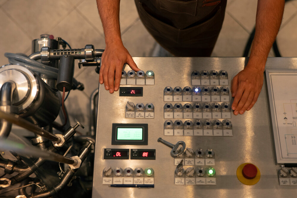
Human Machine Interface (HMI) has become a cornerstone of modern industrial control systems, often working alongside devices like the Wattstopper Dual Technology Wall Mount Occupancy Sensor for enhanced efficiency. By serving as the communication bridge between operators and machinery, HMIs enhance productivity, safety, and operational efficiency. According to Controls Traders, known for its innovative solutions in industrial technologies, HMI panels play a vital role in fostering safe, reliable, and effective work environments.
What is HMI? Definition and Core Applications
So, what does HMI mean? Human-machine interface (HMI) is the technology that facilitates interaction between humans and machines, providing a user-friendly platform for monitoring and controlling industrial processes. According to industry experts, HMI screens empower operators to manage operations effectively, from straightforward tasks to complex automation.
Core Applications:
- Manufacturing: HMI panels provide real-time data and control for production line management, ensuring operational efficiency and reduced downtime.
- Energy Sector: HMI displays are essential for grid management and energy distribution monitoring, supporting a stable and reliable energy flow.
- Logistics: Human Machine Interfaces automate warehouse operations and enhance inventory management through accurate tracking and visualisation.
Common HMI tools include touch panels, graphical user interfaces (GUIs), and integrated HMI displays that interface with PLCs (Programmable Logic Controllers) and other industrial control units.
The Evolution of HMI Technology
HMI technology has significantly evolved, shifting from basic mechanical controls to advanced touch-based and AI-integrated systems. According to Tech Trends Journal, early control systems in the 20th century relied on mechanical switches and indicator lights for basic operations. The introduction of text-based terminals in the 1980s began the shift towards more interactive systems, allowing limited operator interactions.
Key Milestones:
- 1980s: The introduction of text-based terminals began the era of limited interactive HMI screens.
- 1990s-2000s: The emergence of graphical touchscreens revolutionised the field, enabling more complex and visually driven interactions.
- Present Day: HMIs now incorporate AI and cloud technology, offering adaptive, remote-capable, and predictive interfaces that align with digital transformation trends.
Key Features and Benefits of Modern HMI Systems
Modern HMI systems featuring advanced HMI design, enhance operational control and efficiency.
Key Features:
- Real-time Data Visualisation: Operators can see and respond to data instantly, allowing for informed decision-making.
- Custom Interfaces: Flexible layouts tailored to specific processes and operational needs.
- User Accessibility: Intuitive HMI panel for easy navigation and quick onboarding.
- Adaptive Layouts: Configurable displays that evolve with process requirements.
Benefits:
- Enhanced Safety: Integrated safety alarms and alerts notify operators of system anomalies.
- Operational Efficiency: Simplifies complex processes and allows for rapid response to issues.
- Data Analytics Tools: Facilitates predictive maintenance by identifying performance patterns.
- Remote Monitoring: Ensures continuous oversight through remote access, supporting varied operational scenarios.
Applications of HMI in Different Industries
The adaptability of HMI systems allows for their use across various industries, enhancing process optimisation and reducing downtime.
Industry Examples:
- Manufacturing Plants: Real-time HMI displays help monitor production lines, enabling quick adjustments to prevent bottlenecks and delays.
- Energy Facilities: Operators use HMI screens to monitor and control energy outputs, maintaining consistent and reliable distribution.
- Logistics Centres: HMI panels with dashboards track inventory and coordinate vehicle movement, reducing errors and enhancing throughput.
According to a study published by Industry Solutions Weekly, companies using HMI dashboards have significantly improved operational transparency and reduced system failures.
Best Practices for HMI Design and Implementation
The effectiveness of HMI systems largely depends on user-focused HMI design and careful implementation.
Guidelines:
- User Experience (UX) Design Priority: Ensure intuitive and straightforward interfaces.
- Customisation Options: Adaptable configurations to meet specific operational needs.
- Training and Education: Comprehensive training programs maximise system potential.
- Software Compatibility: Seamless integration of HMI software with existing control systems.
- Feedback and Iteration: Regular user feedback to refine the interface.
Challenges and Future Prospects of HMI Technology
Despite many advantages, HMI technology faces challenges and holds promising prospects for the future.
Current Challenges:
- Cybersecurity Risks: Data security must be ensured as HMIs connect to larger networks.
- Legacy System Integration: Compatibility issues with older equipment.
- Complexity in Design: Balancing feature-rich interfaces with user-friendliness.
Future Trends:
- AI-Enhanced Interfaces: Machine learning will drive predictive functions and smarter decision-making.
- Augmented Reality (AR): AR could provide enhanced training and maintenance directly through HMI displays.
- Cloud Connectivity: Expanded cloud-based capabilities for real-time remote access.
The future of HMI points towards smarter, more connected systems that seamlessly integrate with cloud and augmented technologies, promoting productivity and connectivity.
Conclusion
HMI technology has become critical in modern industries, offering real-time control, increased safety, and greater process efficiency. Adopting advanced HMI solutions is essential for companies seeking operational excellence and competitive advantage. As industries progress towards higher levels of automation, embracing cutting-edge HMI technologies positions organisations to optimise their workflows, reduce downtime, and enhance overall productivity.
Explore how Controls Traders can support your HMI needs with expert solutions tailored for the industrial sector. Visit Controls Traders to discover premium HMI products and services that elevate your operations with reliability and innovation. Connect with our team to find the right HMI solution for your business.
FAQs
What does HMI stand for in industrial automation?
HMI stands for Human Machine Interface, facilitating communication between humans and machines.
How does an HMI differ from a PLC?
An HMI is an interactive user interface, while a PLC is an automated system for executing control functions.
What are the key benefits of using HMI in industrial processes?
Improved safety, real-time data access, and streamlined process management.
What challenges exist when implementing HMI technology?
Challenges include cybersecurity, legacy system integration, and design complexity.
What future trends can we expect in HMI technology?
AI-driven enhancements, augmented reality, and cloud-based solutions.
Read more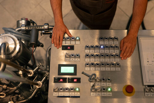
What Are The Different Types of Actuators and Their Applications
Actuators are essential in industrial control systems, converting energy into mechanical motion. Their role in automation and energy conversion helps industries optimise performance, ensuring smoother, more efficient operations. Understanding actuator types aids engineers, facility managers, and manufacturing professionals in selecting the best solutions.
Understanding Different Types of Actuators – A Fundamental Overview
An actuator is a device that converts energy (electric, hydraulic, pneumatic) into mechanical motion. This energy transformation enables movement in systems that control industrial processes and automation. Actuators are responsible for executing commands within control systems, powering everything from robotic arms to valve operations.
Actuators receive input energy and convert it into an output motion. Depending on the actuator type, this motion can be linear or rotary. For instance, electrical energy powers electric actuators, while fluid pressure drives hydraulic actuators. Understanding these principles helps grasp their role in modern industry, especially when exploring current offerings like the Schneider Promo November for innovative solutions and deals.
Linear vs. Rotary Actuators
Differences Between Linear and Rotary Actuators
- Linear Actuators: Produce straight-line motion. Common in conveyor systems, robotic arms, and industrial packaging, they enable precise, repeatable movement.
- Rotary Actuators: Generate circular motion and are vital for rotating machinery parts, automated valves, and assembly lines.
Examples in Industrial Applications
- Linear Actuators: Used in positioning and lifting mechanisms, as seen in assembly robots.
- Rotary Actuators: Essential for rotation processes, such as turning arms in production machinery.
Pneumatic Actuators – Speed and Efficiency
Structure and Characteristics of Pneumatic Actuators
Pneumatic actuators operate using compressed air, enabling fast and repetitive movements. They are known for their simplicity, high-speed operation, and low cost. These actuators are often lightweight and adaptable for various industrial tasks.
Applications
Pneumatic actuators excel in applications requiring rapid, cyclic operations, such as in packaging and bottling plants. Their efficiency makes them suitable for tasks where consistent movement is essential.
Hydraulic Actuators – Power and Precision
The Power of Hydraulic Actuators
Hydraulic actuators leverage fluid pressure to create motion, offering significant force output that is ideal for heavy-duty applications. Their precision and strength are unmatched, making them indispensable for heavy machinery tasks.
Industrial Use Cases
Hydraulic actuators are used in construction equipment like excavators and cranes, where substantial force and precision are needed to lift or move heavy loads. Their robust design ensures reliable operation under high-load conditions.
Electric Actuators – Precision and Control
Benefits of Electric Actuators
Electric actuators offer precise control and are generally low-maintenance. These actuators are powered by electric motors, which are ideal for tasks requiring exact movements and integration with digital control systems.
Practical Applications
Electric actuators are used in automated industrial processes where precision is a priority, such as robotics and conveyor systems. They also support smart systems through programmable controls, enhancing operational flexibility.
If you’re deciding between the two dominant brands for valve and damper actuators, our Belimo vs. Siemens actuator comparison breaks down torque ranges, IP ratings, and Australian stock availability side by side.
Comparing Actuator Types – Selection Guide
Actuator Comparison Table
|
|
|
|
|
|
|
|
|
|
|
|
|
|
|
|
|
|
|
|
|
|
|
|
Choosing the Right Actuator
Select an actuator by evaluating operational speed, force requirements, and environment. Pneumatic actuators suit high-speed, low-force tasks, while hydraulic ones are best for powerful, precise operations. Electric actuators are ideal for applications needing exact control.
In modern variable-flow systems, actuators are increasingly paired with pressure-independent control valves (PICVs), which handle dynamic balancing automatically and allow the actuator to focus purely on modulation.
Key Considerations When Choosing an Actuator
Critical Factors for Selection
- Load Capacity: Assess the force an actuator needs to handle.
- Operational Speed: Choose pneumatic for rapid cycles, hydraulic for power, and electric for controlled motion.
- Environment: Consider exposure to temperature extremes, moisture, or dust.
- Maintenance Expectations: Hydraulic actuators require more upkeep than electric or pneumatic options.
Real-World Applications of Different Actuators
Industrial Use Cases
- Pneumatic Actuators: Utilized in packaging machines where speed and repeatability are key.
- Hydraulic Actuators: Found in construction vehicles and presses due to their power capacity.
- Electric Actuators: Applied in robotic arms for precision assembly and automated adjustments.
Specific Industry Examples
- Manufacturing: Linear actuators in robotic welding.
- Construction: Hydraulic systems in cranes.
- Electronics: Electric actuators in automated testing machines.
Future Trends in Actuator Technology
Advancements Shaping the Industry
Integrating smart actuators and IoT is driving the future of industrial automation. These modern actuators offer enhanced data collection, enabling predictive maintenance and energy savings. The push for eco-friendly and energy-efficient actuators influences the shift towards electric models.
Energy Efficiency and Sustainability
Future trends indicate a move toward sustainable actuators that consume less energy and incorporate recyclable materials. Industries are increasingly adopting electric actuators because they are compatible with renewable energy sources and smart grids.
Conclusion
Actuators are pivotal for industrial processes due to their diverse types and capabilities. Understanding the benefits and limitations of pneumatic, hydraulic, and electric actuators helps select the most suitable solution for optimising operations.
Explore Controls Traders’ extensive range of actuators or contact their expert team for tailored advice in choosing the right actuator for your needs.
Actuators don’t operate in isolation — they’re one part of a broader HVAC control system. For facility managers who want to understand how all the components fit together, our HVAC control systems guide covers the full picture from controllers and sensors through to drives and power protection.
FAQs
What is the best type of actuator for high-speed operations?
Pneumatic actuators are ideal due to their rapid movement and cost-effectiveness.
How do hydraulic actuators compare to electric actuators in terms of maintenance?
Hydraulic actuators require more maintenance due to fluid handling and potential leaks, whereas electric actuators are low maintenance and reliable.
Are electric actuators cost-effective for long-term use?
Yes, despite higher initial costs, electric actuators offer long-term savings in energy and maintenance.
Can I use actuators in harsh outdoor environments?
Hydraulic actuators perform well in rugged conditions, while pneumatic actuators are robust but require dry air to avoid corrosion.
What are the most common applications for linear actuators?
Due to their precise linear motion, linear actuators, such as conveyor lines and robotic arms, are essential in automation systems.
Read more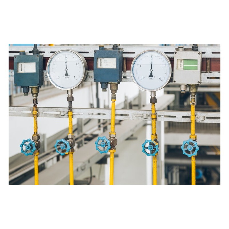
Pressure Switch: Functionality, Types, Applications, Calibration and Safety Features
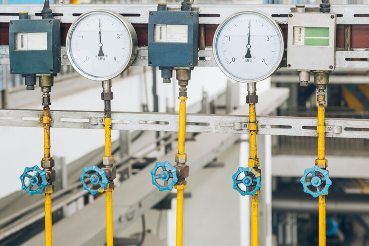
Understanding the multifaceted role of pressure switches is critical for industries reliant on precise pressure management. These devices, integral to systems ranging from water pumps to air compressors, operate by activating or deactivating circuits in response to pressure changes. The diversity of pressure switches—mechanical, electronic, and differential—ensures suitability across varied applications. Accurate calibration, achieved through specialised tools, is paramount for maintaining operational reliability. Additionally, safety features like interlocks and pressure cutout mechanisms are imperative to prevent failures. To comprehend their full impact and functionality, one must explore their types, applications, and safety protocols in greater detail.
What is a Pressure Switch?
According to Controls Traders, a pressure switch is an electrical device designed to monitor and respond to changes in pressure within a system. It operates by detecting when the pressure reaches a predefined threshold and then activating or deactivating a circuit.
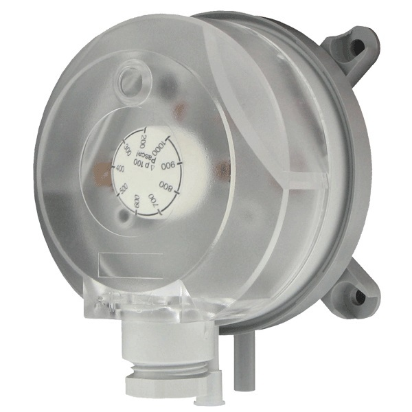
There are two main types: mechanical pressure switches and electronic pressure switches. Mechanical switches use physical mechanisms, while electronic switches utilise pressure sensors.
These devices can monitor various pressure types, such as air pressure and differential pressure. Pressure setting ranges determine the specific pressures at which the switch operates.
Proper pressure calibration guarantees accuracy and reliability. Safety features are integral, preventing system failures and guaranteeing operational efficiency.
Pressure switches are essential in maintaining system integrity and performance in numerous applications, especially when using reliable products from Endress+Hauser.
How Does a Pressure Switch Work?
Understanding the inner workings of a pressure switch involves examining its key components and the mechanisms they utilise to detect and respond to pressure changes. A pressure switch typically consists of a sensor that measures pressure, an electromechanical mechanism to convert pressure changes into electrical signals, and an adjustment range to set specific pressure thresholds.
When the sensed pressure reaches a pre-set level, the switch activates or deactivates an electrical circuit. Calibration guarantees accurate functionality and is essential for maintaining safety features across various applications.
Differential pressure switches operate on similar principles but measure the difference between two pressure points. Their reliability and precision make them indispensable in many industrial and commercial settings.
What are the Types of Pressure Switches?
Several distinct types of pressure switches cater to various industrial and commercial needs.
Mechanical pressure switches operate using a diaphragm or piston mechanism to detect pressure changes.
Electronic pressure switches utilise sensors and digital interfaces for more precise control and monitoring.
Differential pressure switches measure the difference between two pressure points, ensuring accurate readings across a specified pressure range.
Each type has unique calibration requirements and safety features tailored to their specific applications.
Mechanical switches are often preferred for their simplicity, while electronic options offer advanced switching functions and higher precision.
Understanding these types is essential for selecting the right pressure switch for your system's needs and ensuring peak performance and safety.
What Materials are Used in Pressure Switches?
Pressure switches are constructed from various materials to guarantee durability, reliability, and compatibility with different environments and media.
Stainless steel and brass are commonly used for components in contact with media, known as the wetted area, due to their corrosion resistance and strength.
Diaphragms within pressure switches often utilise flexible materials like rubber or metal to detect changes in hydraulic pressure or air pressure switches.
Sensors and pressure transducers are typically made from robust materials to withstand harsh environments.
Electrical contacts, essential for signal transmission, are often crafted from conductive metals.
The choice of materials guarantees the pressure switch performs reliably under varying conditions and extends its operational lifespan.
What are the Physical Dimensions of a Pressure Switch?
When considering the physical dimensions of a pressure switch, it is vital to recognise that these devices can vary considerably in size depending on their specific application and design requirements.
Pressure switches can range from compact designs for limited space applications to larger models suitable for high-pressure capacities.
The physical dimensions are influenced by the type of pressure sensor, safety features, and the inclusion of an adjustment screw for calibration.
Different types of pressure switches cater to various applications, each with unique space constraints and functional demands.
Understanding the physical dimensions is essential for proper installation and ensuring that the pressure switch meets the specific needs of the system it is integrated with.
How to Install a Pressure Switch?
Installing a pressure switch involves gathering the necessary tools and following a series of methodical steps.
Essential tools typically include wrenches, screwdrivers, and a pressure gauge.
The installation process encompasses mounting the switch, connecting wiring, and calibrating the device to guarantee proper functionality.
What Tools are Needed to Install a Pressure Switch?
To install a pressure switch, a specific set of tools is required to guarantee proper functionality and safety.
Essential installation tools include a pressure gauge to monitor system pressure, a control valve for flow regulation, and a pressure regulator to maintain desired pressure levels.
Additionally, tools for connecting to the electrical circuit are necessary, such as wire strippers and screwdrivers.
For systems involving water pressure, float switches may be required. An air compressor can aid in pressurising the system for testing purposes.
Adhering to safety features is vital; hence, personal protective equipment (PPE) like gloves and safety glasses should be used.
Proper tools assure the pressure switch operates effectively and maintains system integrity.
What are the Steps to Install a Pressure Switch?
Proper installation of a pressure switch involves several systematic steps to guarantee reliable operation and system safety.
Start by ensuring the system is de-energised to meet safety features.
Identify the correct location for the pressure switch installation near the inlet pressure source.
Connect the pressure switch to the pneumatic or fluid pressure line, ensuring all fittings are secure.
Adjust the pressure settings according to system requirements.
Use a calibration device to verify accuracy.
Connect the electromechanical control pressure switch to the electrical system, following wiring diagrams.
Power up the system and test the pressure switch to confirm it responds correctly to changes in pressure.
What are Common Applications of Pressure Switches?
Pressure switches are commonly used in a variety of industrial, commercial, and residential applications to monitor and control pressure levels.
In water pumps, they guarantee proper pressure and prevent damage due to overpressure. Air suspension systems in vehicles utilise pressure switches to maintain ideal ride quality. Compressors use them to regulate air pressure and avoid system failures. In flow control, they help manage fluid dynamics in pipelines. Wastewater treatment facilities use pressure switches to maintain safe and efficient operations.
These devices are integral to automation control products, providing essential feedback and enabling automated responses. Safety features and precise calibration are critical in all these applications to guarantee reliability and performance.
How to Calibrate a Pressure Switch?
Calibrating a pressure switch requires specific equipment such as a pressure source, a calibrated pressure gauge, and adjustment tools.
The process involves setting the switch to the desired pressure range and fine-tuning the set points to guarantee accurate operation.
Following a systematic approach, involving precise steps, assures the switch functions reliably within its designated parameters.
What Equipment is Needed to Calibrate a Pressure Switch?
To calibrate a pressure switch, specific equipment such as a pressure source, a reference gauge, and a calibration device is essential. The pressure source provides the necessary psi for testing.
Pressure gauges and sensors guarantee precise pressure management by displaying accurate measurement values. Transducers convert pressure into an electrical signal that can be read by the calibration device.
This device compares the pressure switch's response to the known reference values, affirming its accuracy. Adjustable pressure settings on the calibration device allow for fine-tuning to match the desired operational parameters.
Proper calibration guarantees reliable performance, contributing to the overall safety and efficiency of any system using pressure switches.
What are the Steps to Calibrate a Pressure Switch?
Effective calibration of a pressure switch involves several methodical steps to ascertain accurate and reliable operation.
Begin by isolating the pressure switch from the system to guarantee safety. Connect a calibrated pressure source to the switch. Gradually apply mechanical pressure or electronic pressure until the switch point is reached.
Adjust the switch to the desired preset pressure level. Next, reduce the pressure to determine the reset point. Measure and record hysteresis, the difference between the switch point and reset point.
Make necessary adjustments to achieve peak performance. Repeat the process to confirm accuracy. Proper calibration enhances service life and guarantees reliable water pressure control.
Always follow manufacturer guidelines and use precise instruments for best results.
What are the Safety Features of a Pressure Switch?
A pressure switch incorporates several safety features designed to prevent system failures and guarantee reliable operation.
High pressure and low pressure switches are equipped with interlocks to protect equipment by shutting down systems when pressure levels exceed safe limits.
Pressure cutout mechanisms are essential for preventing over-pressurisation, which could lead to hazardous conditions.
In explosion-hazard environments, pressure switches are designed to minimise the risk of triggering explosions.
Additionally, maintaining consistent water pressure and managing pressure differentials are critical safety features that maintain system stability.
These features collectively enhance the reliability and safety of pressure switches across various applications, making them indispensable for maintaining operational integrity and preventing potential damage or accidents.
How to Troubleshoot a Pressure Switch?
When troubleshooting a pressure switch, it is essential to first identify common issues such as incorrect pressure settings, electrical faults, or mechanical wear.
Understanding the latest innovations in pressure switch technology, including digital interfaces and advanced diagnostics, can aid in more effective problem-solving.
Additionally, new materials like corrosion-resistant alloys and high-performance polymers enhance durability and reliability.
What are Common Issues with Pressure Switches?
Common issues with pressure switches often stem from improper calibration, electrical problems, or mechanical failures.
Calibration errors can lead to inaccurate pressure readings, affecting the performance of the pressure switch and associated systems.
Electrical problems, such as faulty wiring or loose connections, can disrupt the signal transmission between the pressure switch and control unit.
Mechanical failures, like worn-out diaphragms or clogged pressure ports, can prevent the pressure switch from operating correctly.
Pressure spikes and pump damage can occur if the sensor type electromechanical pressure switch fails to provide adequate protection on water pumps.
Regular maintenance and calibration are essential to guarantee the safety features and applications of pressure switches function effectively, mitigating common issues and maintaining system integrity.
What are the Latest Innovations in Pressure Switch Technology?
Advancements in pressure switch technology have led to the development of more accurate, reliable, and versatile devices suitable for a wide range of applications.
Among the latest innovations are digital displays and multicolour switching displays, enhancing functionality and user interface.
Modern electromechanical pressure switches now offer improved calibration features, guaranteeing precision and consistency.
These innovations enable more efficient monitoring and control in various types of applications, from industrial automation to HVAC systems.
Enhanced safety features have also been integrated, providing better protection against overpressure conditions.
These technological advancements guarantee that pressure switches remain indispensable tools for maintaining operational safety and efficiency.
What New Materials are Being Used in Pressure Switches?
Recent developments in material science have introduced advanced composites and high-performance alloys into the construction of pressure switches, greatly enhancing their durability and functionality.
These new materials improve the performance of components and sensors under extreme temperature conditions, making them ideal for specialist industry applications. Enhanced materials also contribute to more accurate calibration, resulting in better reliability and safety features.
In demanding environments, such as chemical processing or oil and gas extraction, these pressure switches exhibit resilience and precision, ensuring peak performance.
The integration of these advanced materials into pressure switch design reflects a significant step forward in meeting the rigorous demands of modern applications, ultimately broadening their scope of use and effectiveness.
Read more

Comprehensive Guide to Stand-alone Controllers & Thermostats
Stand-alone controllers and thermostats are essential components in modern building automation systems, often integrated with safety solutions from Gas Alarm Systems. These smart HVAC controllers control various aspects of a building, such as temperature, humidity, and lighting.
This comprehensive guide will discuss everything you need to know about a stand-alone controller and thermostats and why they improve energy efficiency.
What Are Stand-alone Controllers?
Stand-alone controllers are designed to manage HVAC systems without installing a Building Management System (BMS). They control temperature, humidity, and air quality by directly interfacing with heating and cooling units. These standalone controllers are particularly beneficial in smaller buildings or remote locations where centralised control is impractical. However, larger systems tend to have issues with scalability to offer a balanced view.
What are the Key Features of Stand-alone Controllers?
Some of the critical features of a stand-alone access control system include:
- User-friendly interface: Stand-alone controllers typically have a simple and intuitive user interface, making them easy to operate.
- Programmability: These controllers can be programmed to follow specific schedules or adjust settings based on occupancy patterns, resulting in energy savings.
- Remote access: Some stand-alone controllers have remote access capabilities, allowing users to control the system from anywhere through a web or mobile application.
- Compatibility: Stand-alone controllers are compatible with various HVAC systems, making them suitable for multiple building types and sizes.
- Security features: These controllers have built-in features such as user authorisation, access control lists, and encryption to ensure the system's safety.
Types of Stand-alone Controllers
There are various types of stand-alone controllers.
- Temperature Control Valves (TCV): TCVs regulate water flow based on temperature settings. They ensure the HVAC system maintains the desired thermal performance even under varying load conditions. This type of control is crucial in applications where precise temperature management is essential.
- Pressure-Independent Control Valves (PICV): PICVs automatically adjust the water flow to maintain consistent performance despite changes in system pressure. They enhance energy efficiency by optimising flow rates according to real-time demands.
- Automatic Balancing Valves (ABV): ABVs help maintain proper flow rates by automatically adjusting to pressure fluctuations within the system. This ensures that each part of the HVAC system receives the appropriate amount of heating or cooling.
HVAC Thermostats: The Heart of Temperature Control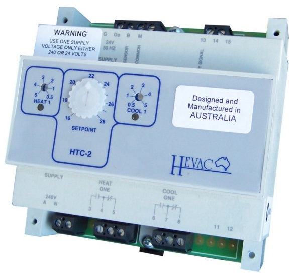
Thermostats are integral components within HVAC systems that monitor and regulate temperature. Stand-alone thermostats function independently, allowing users to set up desired temperatures without interfacing with a central control system. Smart thermostats have gained popularity recently due to their advanced features and benefits.
One of the main advantages of smart thermostats over traditional ones is their energy efficiency. They can automatically adjust the temperature based on usage and occupancy patterns, making them more efficient and convenient.
Types of HVAC Thermostats:
- On/Off Thermostats: These basic thermostats turn heating or cooling systems on or off based on a set temperature threshold. While straightforward, they can lead to temperature fluctuations. Examples include the Honeywell Pro Non-Programmable Digital Thermostat, a reliable choice for those seeking basic functionality with a backlit display for easy visibility. Users appreciate its simplicity and accuracy.
- Proportional Thermostats: Proportional thermostats provide more precise control by modulating system output based on current temperature readings. This results in improved comfort and energy efficiency. Popular brands include Ecobee Smart Thermostat Premium and Google Nest Learning Thermostat.
- Multi-Zone Thermostats: Designed for larger spaces, multi-zone thermostats allow for independent temperature control in different building areas. This zoning capability enhances comfort and reduces energy consumption. A well-known brand is the Honeywell Home T9 WiFi Smart Thermostat, which includes room sensors that detect occupancy and temperature.
Advantages of Stand-alone Controllers and Thermostats
- Flexibility: Stand-alone boost controller devices can be installed in various locations without extensive wiring or integration with existing systems.
- User-Friendly: Most stand-alone controllers feature intuitive interfaces that make it easy for users to adjust settings as needed.
- Reliability: With fewer components than centralised systems, stand-alone controllers often have lower failure rates.
Applications of Stand-alone Controllers and Thermostats
Stand-alone controllers and thermostats are widely used across the world in different sectors:
- Residential Buildings: Homeowners utilise stand-alone thermostats for efficient heating and cooling management.
- Commercial Spaces: Offices and retail environments benefit from multi-zone thermostats that cater to varying occupancy levels.
- Industrial Settings: In warehouses or manufacturing facilities, stand-alone units help maintain optimal product and personnel conditions.
- Remote Locations: Buildings without access to centralised control systems rely on stand-alone solutions for effective climate management.
How Can You Choose the Right Controller or Thermostat
When selecting a stand-alone thermostat for your HVAC system, consider the following factors:
- Application Needs: Assess whether you require basic on/off control or more advanced proportional control features.
- System Compatibility: Ensure the chosen device is compatible with your HVAC equipment.
- User Interface: Look for intuitive controls that match your comfort level with technology.
- Energy Efficiency Features: Consider devices that offer energy-saving modes or innovative capabilities for enhanced efficiency.
Comparison Table: Cost vs. Features of Controllers/Thermostats
|
|
|
|
|
|
|
|
|
|
|
|
|
|
|
|
|
|
|
|
|
|
|
|
|
|
|
|
|
|
|
|
|
|
|
|
|
|
|
|
|
|
|
|
|
Wrap Up
Stand-alone controllers and HVAC thermostats are essential for managing indoor climates effectively and efficiently. Their independence from centralised systems allows for greater flexibility in operation, cost savings, and user convenience. By understanding the various types available and their specific applications, users can make informed decisions that enhance comfort while optimising energy use in their buildings.
FAQs
Can stand-alone controllers work with any HVAC system?
Most stand-alone controllers are compatible with various HVAC systems, but it's always best to check for compatibility before purchasing.
How do stand-alone thermostats differ from centralised control systems?
Stand-alone thermostats operate independently and can be installed in various locations without extensive wiring or integration with existing systems. In contrast, centralised control systems require more complex installation and management processes.
Are there any maintenance requirements for stand-alone controllers and thermostats?
Like any other HVAC equipment, stand-alone controllers and thermostats require regular maintenance to ensure optimal performance and longevity. The manufacturer's guidelines provide specific maintenance recommendations.
Can stand-alone controllers and thermostats be integrated into a centralised control system?
Stand-alone controllers and thermostats can sometimes be integrated into a centralised control system for more comprehensive management. However, this may require additional equipment and professional installation.
Do stand-alone controllers and thermostats have any energy-saving features?
Many stand-alone controllers and thermostats offer energy-saving modes or advanced features to optimise energy use within the HVAC system. Be sure to research different options to find the most suitable one for your needs.
Can stand-alone controllers integrate with smart home systems like Google Home or Amazon Alexa?
Yes, many modern stand-alone controllers are designed to be compatible with smart home ecosystems, enhancing user convenience and control options.
Read more
Smart HVAC Controllers for Commercial Use: Top Solutions for Energy Efficiency
Smart HVAC controllers for commercial use are increasingly vital in commercial settings and often rely on reliable accessories like the MR60 Battery Lead 10A for dependable power connections. They provide enhanced energy efficiency, cost savings, and improved comfort. These systems leverage advanced technology to optimise heating, ventilation, and air conditioning, addressing the significant energy consumption typical of commercial buildings.
What are the Benefits of Smart HVAC Controllers?
Smart HVAC controllers offer a range of advantages that enhance energy efficiency, comfort, and overall system performance in commercial buildings. Here are the key benefits:
- Enhanced Energy Efficiency: Commercial HVAC control systems optimise energy use through real-time adjustments based on occupancy and environmental conditions, achieving energy savings of up to 20% or more than traditional systems.
- Improved Comfort and Productivity: These systems maintain precise temperature control, adapting to user preferences and ensuring a comfortable environment that can boost workplace productivity.
- Extended Lifespan of HVAC Systems: Predictive maintenance features monitor system performance and alert users to potential issues, helping to prolong equipment lifespan and reduce repair costs.
- Increased Security with Remote Monitoring: Remote access allows building managers to monitor HVAC operations in real time, enhancing security with alerts for unusual activities.
- Cost Reduction through Optimized Energy Consumption: Intelligent HVAC systems significantly lower utility bills by adjusting operations around peak energy usage times, providing financial benefits over time.
Smart HVAC controllers are integral to modernising heating and cooling systems in commercial buildings. They enhance energy efficiency and comfort and extend the lifespan of equipment while providing cost savings and improved security through advanced monitoring capabilities.
Types of Smart HVAC Controllers
Smart HVAC controllers come in various types, each offering unique features to enhance energy efficiency and user convenience:
- Wi-Fi-enabled thermostats allow remote access and control via smartphones or tablets, enabling users to adjust settings from anywhere.
- Smart Thermostats with Built-in Sensors: Equipped with sensors for monitoring temperature and humidity, these thermostats can optimise indoor climate based on real-time conditions
- Integrated Building Management Systems (BMS): These systems provide comprehensive control over HVAC, lighting, and other building systems, facilitating centralised management for extensive facilities.
- Cloud-based HVAC Controllers: These controllers utilise cloud technology to enhance performance tracking and energy management by offering real-time monitoring and analytics.
- Voice-controlled thermostats: These thermostats are compatible with Google Assistant and Amazon Alexa, enabling hands-free operation through voice commands, making home automation convenient.
Key Features of Smart HVAC Controllers
Here are the key features of Smart HVAC controllers.
- Energy Efficiency Features: Smart HVAC controllers offer advanced scheduling and geofencing capabilities to optimise energy consumption based on user patterns and occupancy.
- Remote Control and Monitoring: Users can control HVAC systems remotely via mobile apps, allowing adjustments from anywhere and enhancing convenience and energy management.
- Advanced Sensors: Equipped with sensors for temperature, humidity, and air quality monitoring, these systems gather real-time data to ensure optimal indoor conditions.
- Integration with Smart Devices: Smart HVAC systems can seamlessly integrate with other smart home devices, enabling coordinated control for improved efficiency.
- Customisable Features: Users can customise commercial HVAC control settings to meet specific comfort needs, utilising features like learning algorithms that adapt to individual preferences over time.
Final Wrap
Smart HVAC controllers are a crucial component of energy-efficient commercial buildings. They offer a range of benefits, including energy efficiency, comfort, and security. Various smart HVAC controllers are available, each with unique features and benefits. Building management systems (BMS) offer comprehensive control and monitoring of HVAC systems. Implementing smart HVAC controllers requires careful planning and execution but offers long-term benefits and savings.
FAQ
How do Smart HVAC Controllers improve energy efficiency?
They utilise real-time data from sensors to adjust heating and cooling based on occupancy and environmental conditions, potentially saving up to 20% on energy costs compared to traditional systems.
What types of Smart HVAC Controllers are available?
Common types include Wi-Fi-enabled thermostats, smart thermostats with built-in sensors, integrated building management systems (BMS), cloud-based controllers, and voice-controlled thermostats
Can Smart HVAC Controllers be monitored remotely?
Yes, many innovative HVAC systems offer remote monitoring capabilities, allowing facility managers to control and adjust settings via mobile apps from anywhere
What are the key features of Smart HVAC Controllers?
Key features include advanced scheduling, geofencing, remote control, integration with other smart devices, and customisable settings that adapt to user preferences
Do Smart HVAC Controllers require unique installation?
While some systems can be easily installed by users, others may require professional installation for optimal integration with existing building systems
Read more
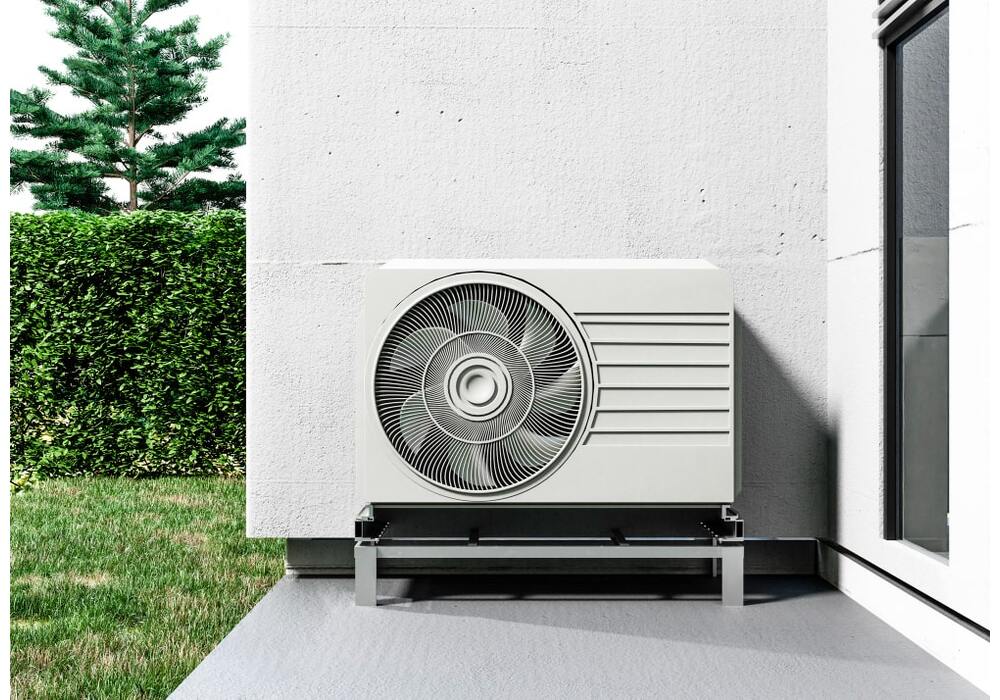
The Role of Smart HVAC Controllers in Energy Efficiency for Commercial Buildings
Nowadays, when energy efficiency is paramount, commercial buildings increasingly turn to technology to optimise their heating, ventilation, and even air conditioning unit (HVAC) systems to save money. The intelligent HVAC controller is one of the most significant advancements in this area, often supported by reliable backup power like the AUS Cell 12V Battery 9Ah with Custom Plug and Label.
This piece by Control Traders explores the role of intelligent HVAC controllers in home climate and enhancing energy efficiency, their benefits, types, features, installation, maintenance, and their integration into smart home systems.

What is a Smart HVAC Controller?
A smart HVAC controller is an intelligent device that allows users to manage their HVAC systems remotely through smartphones or tablets. These energy-efficient HVAC devices, including heat pumps and ducted systems, can be integrated with air conditioners. By leveraging advanced algorithms and real-time sensor data, intelligent HVAC controllers optimise the performance of heating and cooling systems to maintain comfort while minimising energy consumption.
Key Functions
- Remote Monitoring and Control: Users can adjust settings from anywhere, ensuring optimal performance even when not on-site.
- Data Analytics: Many smart controllers provide insights into energy usage patterns, allowing for informed decision-making regarding energy consumption.
- Automation: They can adjust settings based on occupancy or time of day, increasing efficiency.
Benefits of Smart HVAC Controllers
Energy Savings
One of the core advantages of smart HVAC controllers is their ability to reduce energy consumption significantly. By optimising system performance through real-time adjustments to the right temperature based on occupancy and weather conditions, businesses can expect a reduction in energy bills ranging from 10% to 40%. In addition to reducing operating costs, this contributes to sustainability efforts by reducing carbon footprints.
Improved Indoor Air Conditioning
By using air quality sensors regulating temperature, humidity, and ventilation rates, smart HVAC controllers monitor air quality within buildings. These air conditioning systems contribute to better indoor environments by lowering allergens and pollutants by maintaining ideal conditions. Increased worker happiness and productivity can be attributed to better air quality.
Enhanced Comfort
With remote access capabilities, users can easily monitor and adjust temperature settings from their devices. This flexibility allows for personalised climate control that accommodates varying preferences among occupants. Scheduling features enable businesses and family members to set specific temperature profiles for different times of the day or week, ensuring comfort during working hours while saving energy during off-hours.
Increased Convenience
Integration with smart home systems adds another layer of convenience. Users can remotely control their HVAC systems alongside other smart devices through one app, single interface or voice commands via platforms like Amazon Alexa or Google Home. This interconnectedness simplifies management and enhances user experience.
Types of Smart HVAC Air Conditioning System Controllers
Understanding the different types of intelligent HVAC controllers available can help businesses choose the right solution for their needs:

Wi-Fi Adapters
These devices can be retrofitted onto existing HVAC units to enable remote control capabilities without replacing the entire system. They serve as a bridge between traditional units and modern innovative technology.
Smart Thermostats
Smart thermostats are designed specifically for smartphones. They can be used to control temperature settings and schedule adjustments. They often come equipped with learning capabilities that adapt to user preferences over time.
Comprehensive Smart HVAC Systems
These systems integrate multiple climate control components into one cohesive unit, allowing for advanced heating, cooling, intelligent air conditioning, and ventilation management across large commercial spaces.
Features to Look for in a Smart HVAC Controller
When selecting an intelligent HVAC controller, consider the following essential features:
Remote Control Capabilities: Ensure the controller allows easy monitoring and adjustments via smartphones or tablets.
Scheduling and Automation: Look for features that enable users to set schedules based on occupancy patterns or specific times of day to optimise energy efficiency.
Air Quality Monitoring: Controllers with sensors that detect pollutants or humidity levels can automatically adjust settings to maintain healthy, sensible air quality.
Smart Home Integration: Compatibility with popular smart home platforms enhances convenience and allows for seamless control and management alongside other devices and accessories.
Versatility: Choose a controller that supports various HVAC systems to ensure compatibility with your house and existing infrastructure.
How Smart HVAC Controllers Work
Smart HVAC systems connect with HVAC systems using wireless technologies such as Wi-Fi or Zigbee. They gather data from various sensors, monitoring factors like temperature, humidity, room occupancy levels, and even external weather conditions to make real-time informed adjustments.
Programming and Automation
Users can program these controllers to operate under specific conditions; for example:
- Geofencing: The system detects when occupants leave or arrive at the building and adjusts temperature settings accordingly.
- Learning Algorithms: Some models learn user preferences over time and automatically adjust settings based on past behaviour.
Choosing the Right Smart HVAC Controller
Selecting the appropriate energy-efficient AC systems involves several considerations:
- Compatibility: Assess whether the controller is compatible with your existing HVAC system.
- Required Features: Based on your operational needs, determine which features are most important (e.g., air quality monitoring vs. essential temperature control).
- Energy Efficiency Potential: Research how different models perform regarding energy savings. Energy efficiency in HVAC systems helps you to avoid interruptions due to energy-related issues.
- User Reviews: Read reviews from other users to gauge reliability and performance.
- Cost vs. Value: Compare prices while considering long-term savings potential.
Installation and Setup
The installation process varies depending on the type of intelligent HVAC controller:
- DIY Options: Some controllers are designed for easy installation by users without professional help.
- Professional Installation: Hiring a professional may be necessary for more complex systems or integrations.
Always refer to manufacturer instructions during setup to ensure proper configuration.
Maintenance and Troubleshooting
To keep smart HVAC controllers functioning optimally:
- Regularly check and replace air filters or heat pumps.
- Update software and firmware periodically for security enhancements.
- Address common connectivity issues promptly by troubleshooting network connections or wifi adapters.
Energy Efficiency and Cost Savings
The financial benefits of implementing smart HVAC controllers are significant:
- Reduced Energy Consumption: By optimising system performance through automation and real-time adjustments.
- Lower Utility Bills: Businesses often see reductions in monthly energy expenses.
- Increased Asset Lifespan: Efficient operation reduces wear and tear, extending the lifespan of equipment and reducing replacement costs.
According to the U.S. Department of Energy, buildings with smart controls can achieve substantial energy savings without sacrificing comfort, making them an attractive investment for commercial property owners.
Smart Home Integration
Smart HVAC controllers can seamlessly integrate into broader smart home ecosystems:
- Compatibility with platforms like Amazon Alexa or Google Assistant allows users to control their systems through voice commands.
- Integration with other smart devices enables coordinated management—such as adjusting lighting based on temperature settings—enhancing overall building efficiency.
Remote Access and Control
For building managers, remote monitoring is a game-changer:
- Users receive alerts directly on their smartphones regarding system performance issues or maintenance needs.
- Remote access allows quick adjustments during off-hours or emergencies without needing physical presence on-site.
Final Thoughts
Smart HVAC controllers play a pivotal role in enhancing energy efficiency within commercial buildings by optimising climate control systems while improving comfort levels for occupants.
Their ability to provide total control, remote access, automation features, sensible air pro monitoring capabilities, and integration with smart home technologies make them invaluable tools in modern building management strategies.
Don't miss out on smart HVAC controllers' potential cost savings and convenience—consider implementing them in your commercial building today. For more information, contact us at 1300 740 140.
FAQs
What is smart HVAC control?
Smart HVAC, or intelligent climate control, refers to using technology, such as sensors and automation, to optimise the performance of building heating, ventilation, and air conditioning (HVAC) systems. This can include features like remote access, scheduling and automation, air quality monitoring, and integration with other smart home devices.
How much does a smart HVAC system cost?
The average cost to set up a new system would be about $10,000. Prices range considerably, from luxurious installations that cost up to $15,000 to more affordable choices that cost $5,000.
How can I make my HVAC smart?
You will need a compatible intelligent HVAC controller to make your smart HVAC control system smart. This device connects wirelessly to your existing HVAC system and enables it to be controlled through automation and remote access. Ensure that the controller is compatible with your current system before purchasing. Once installed, follow the manufacturer's instructions for setup and programming.
Can I make my ducted aircon smart?
Yes, you can make your ducted air conditioner a thoughtful air by installing a compatible Smart HVAC controller. This device will allow you to control your indoor unit and air conditioning system through automation and remote access.
Before purchasing, check the controller's compatibility with your specific ducted air conditioner model. Once installed, follow the manufacturer's instructions for setup and programming.
Read more

VEGA Guided Radar
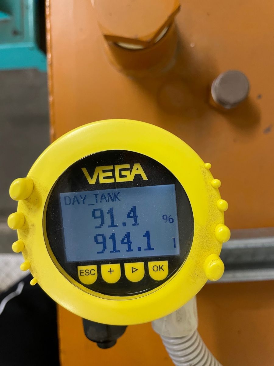
This is a great product. Highly accurate and able to measure within very tight tolerances. Reach out to our team for more information!
Read more
How to Integrate UPS Systems Into Your HVAC Controls
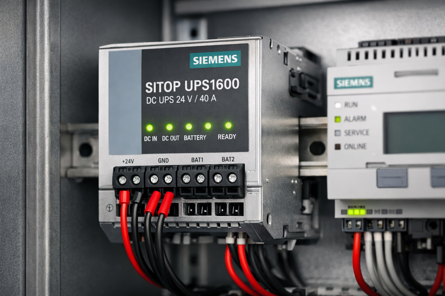
For facility managers and controls engineers, "uptime" is the only metric that matters. While we often focus on mechanical redundancy—N+1 chillers or twin-head pumps—the digital infrastructure controlling that plant is frequently left vulnerable to power quality issues.
A momentary voltage sag or "brownout" can reboot a Building Management System (BMS) controller, causing a loss of visibility, data corruption, or the reset of critical control loops.
At Controls Traders, we stock a range of [Industrial UPS Systems] alongside our controllers and actuators to ensure your plant room stays online,. Here is a technical guide on how to correctly size and integrate a UPS into your HVAC strategy.
1. Why HVAC Controls Require UPS Backup
It is a common misconception that a UPS is only for the server room. Modern HVAC control panels contain sensitive electronics that are highly susceptible to "dirty power."
- Reboot Latency: A high-level controller (like a Niagara JACE or a server-level supervisor) can take 5–10 minutes to reboot after a 2-second power blip. During this time, your plant is running blind.
- Data Integrity: Sudden power loss can corrupt trend logs and historical databases, creating compliance gaps for critical environments like hospitals or labs.
- Component Protection: Frequent power spikes can degrade the capacitors in power supplies and actuators over time.
2. Equipment Typically Supported
You do not need to put the entire mechanical switchboard on a UPS. The goal is to keep the "brains" alive. Critical loads typically include:
- BMS Controllers: The primary DDC or Head-End units.
- Network Hardware: Ethernet switches and routers that facilitate communication between the plant room and the operator workstation.
- Field Power Supplies: The 24V DC/AC transformers powering sensors and critical actuators.
- HMIs: Touch screens on local control panels,.
3. Types of UPS Systems
When browsing our [Industrial UPS Systems] category, you will generally encounter two main topologies. Note: Industry standards dictate the following distinctions:
- Line-Interactive: Good for general voltage regulation. It boosts or trims voltage fluctuations without switching to battery. Suitable for standard network switches.
- Online (Double Conversion): The gold standard for critical BMS controllers. It constantly converts AC to DC and back to AC, providing a perfect sine wave with zero transfer time. This isolates your sensitive electronics from raw utility power.
4. How to Size a UPS
Sizing is a simple calculation of load versus runtime.
- Calculate Total Load: Add up the power consumption (Watts or Amps) of every device in the panel.
- Example: Controller (20W) + Switch (15W) + 24V Power Supply load (100W) = 135W.
- Convert to VA: UPS systems are rated in Volt-Amperes (VA). A safe rule of thumb for computer electronics is to divide Watts by 0.7 (Power Factor).
- Calculation: 135W / 0.7 ≈ 192 VA.
- Apply Headroom: We recommend sizing the UPS at least 25% above your calculated VA to handle inrush currents during startup. In this example, a 500VA or 750VA unit would be appropriate.
5. Installation Notes
Integrating a UPS into a mechanical switchboard requires planning:
- Heat Dissipation: UPS batteries degrade rapidly in heat. Ensure the control cabinet is ventilated. If the plant room is consistently above 30°C, consider moving the UPS to a conditioned IT closet and running a dedicated power feed.
- DIN-Rail Mounting: For tidy panels, look for industrial UPS units that mount directly to the DIN rail, rather than sitting loosely in the bottom of the enclosure.
- Dry Contacts: Integrate the UPS status into your BMS. Most industrial units have a dry contact output for "On Battery" or "Low Battery." Connect this to a digital input on your controller so you get an alarm before the battery dies.
6. Maintenance and Testing
A UPS is a consumable item.
- Battery Replacement: Lead-acid batteries typically last 3–5 years. Schedule proactive replacement.
- Self-Test: Many modern units perform automatic self-tests, but a manual function test (cutting mains power to the panel) should be part of your annual preventative maintenance.
7. Summary
Integrating a UPS is a small investment that protects the expensive "brains" of your building. It prevents nuisance alarms, protects hardware from dirty power, and ensures you maintain visibility during short outages.
At Controls Traders, we supply the necessary components to build reliable control panels, from Power Supplies and Relays to complete backup solutions.
Read more