


Welcome to Controls Traders, located in Adelaide, South Australia. We are a supplier of quality building automation controls and peripheral products for the HVAC industry. We stock a full range of controllers, sensors, valves and actuators, damper actuators and accessories to suit any application. Our aim is to provide our customers with the highest level of service, from sales to delivery and after sales support. With our extensive in-house knowledge and expertise in the industry, we can advise you on selection and application of our wide range of controls products.

Backed by 40 years industry experience. When you just need to be sure.

No, we’re serious. Anywhere. Anytime.

We stock all major global brands. And if we don’t have it, we’ll find it.

We warehouse the stock so you don’t have to wait.
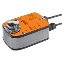
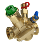
$144.26 $171.75 ex GST

The choice between spring-return and non-spring-return actuators is one of the most consequential specification decisions in HVAC and building automation. These two types behave entirely differently when power is cut or a control signal is lost — and specifying the wrong type can result in freeze-damaged coils, failed fire control sequences, or unnecessary capital expenditure across a large installation.
Selection should be driven by the fail-safe requirement of the specific application — not by habit, default specifications, or cost alone. To make the correct choice, you must understand what happens to the connected damper or valve when power is lost, and whether that outcome is acceptable given the system, its occupants, and the applicable Australian Standards. This guide sets out the technical differences, code obligations, and a practical decision framework for the most common HVAC applications.
A spring-return (SR) actuator uses an electric motor to drive a gear train that rotates the output shaft — and simultaneously compresses an internal coil spring. When the motor is de-energised (power removed, or control signal lost), the compressed spring releases and drives the shaft back to its starting, or fail-safe, position.
Spring-return actuators are available in two fail-safe configurations, which must be specified at time of order:
The fail-safe position is set at manufacture and cannot be reversed in the field. Always specify NC or NO on the purchase order. An important operational characteristic of spring-return actuators is that they draw continuous electrical power at any intermediate modulating position — the motor must continuously counteract the spring force to hold the shaft at positions other than the fail-safe position.
A non-spring-return (NSR) actuator uses an electric motor to drive a self-locking worm gear that positions the output shaft. When the motor stops, the worm gear holds the shaft in position without any motor power — the worm gear geometry prevents back-driving, so air pressure, valve pressure, and gravity cannot move the shaft. On power loss, the result is hold-in-last-position: the shaft remains exactly where it was when power was cut.
Electronic fail-safe (capacitor-return) actuators exist as a variant that offers some of the size and power efficiency advantages of NSR actuators while providing a defined fail-safe position. These actuators store energy in an internal capacitor and, on power loss, use that stored energy to drive to a pre-programmed position. However, this approach relies entirely on the capacitor being functional — periodic testing and capacitor replacement are required to maintain the fail-safe behaviour, and capacitor-return actuators are not to be used in life-safety applications where spring-return is mandated by Australian Standards. For life-safety applications, mechanical spring-return remains the only compliant option.
The power draw of an NSR actuator holding position is less than 0.5 W, compared to 2–5 W continuously for a spring-return actuator holding an intermediate modulating position. In large installations with many actuators, this energy difference is measurable over a year of operation.
| Feature | Spring-Return | Non-Spring-Return |
|---|---|---|
| Fail-safe position | Defined at manufacture (open or closed) | Holds last position (or programmable with capacitor — see note) |
| Code requirement for life-safety | Mandatory (fire/smoke dampers, OA dampers) | Not acceptable for life-safety applications |
| Operating power draw | Higher — motor continuously counteracts spring | Lower — worm gear holds position without motor power |
| Physical size for same torque | Larger — spring housing adds bulk and mass | More compact |
| Capital cost | Higher (typically 30–60% above equivalent NSR) | Lower |
| Mechanical life | Spring fatigue over time; check manufacturer cycle rating | Longer mechanical life in most applications |
| Manual override | Most include pushbutton or hex key override | Most include a manual override |
Spring-return actuators are not an option in applications where a defined fail-safe position is required by Australian Standards or by the consequences of the application. Understanding these requirements before specifying is essential.
Fire and smoke dampers (AS 1668.1, AS 1851): Spring-return is mandatory for all fire and smoke damper actuators. The actuator must drive to the closed position on loss of electrical power or on a trip signal from the fire control panel. Non-spring-return actuators — including capacitor-return variants — are not compliant for this application. Auxiliary switch outputs providing proof-of-closure contacts are also required; confirm the switch configuration (normally-open or normally-closed contact, and the voltage and current rating) against the fire control panel specification before ordering.
Outdoor air dampers in most Australian applications: AS 1668.2 cold-air protection requirements and standard engineering practice require OA dampers to close on power loss in virtually all Australian commercial HVAC applications. This includes temperate climate zones such as Adelaide, Melbourne, and Canberra, where winter temperatures create freeze risk for chilled water coils and heating coils. Spring-return NC is the correct specification for OA damper actuators across the overwhelming majority of Australian commercial projects.
Beyond code obligations, spring-return should also be specified in any application where the consequence of the actuator failing to reach a defined position is operationally significant — including applications where the BMS cannot guarantee a prompt command to the actuator following power restoration, valves on high-pressure steam or high-temperature hot water circuits where an open valve during power failure would be hazardous, and applications in buildings where the BMS has a history of losing control of actuators during power disturbances.
VAV box primary air dampers in most commercial buildings: Hold-in-last-position is acceptable for the primary air damper in a standard VAV terminal unit in commercial office, retail, or education applications. The majority of VAV actuator installations in Australian commercial buildings use NSR actuators. Belimo LM series and Siemens SAS series both offer NSR variants specifically suited to VAV terminal mounting. Where the project specification or brief explicitly requires spring-return on VAV boxes — for example, for specific critical-environment zones — spring-return must be used; but it is not the default requirement for commercial VAV applications.
Modulating mixing box dampers in mild climates: Where freeze protection of coils is not a concern and the system includes independent safeguards (such as a low-limit temperature controller), an NSR actuator on a mixing box return-air or relief-air damper may be acceptable. This requires a documented fail-safe analysis and sign-off from the mechanical engineer responsible for the project — it is not a blanket permission.
Cost-constrained applications with appropriate fail-safe analysis: Where capital cost is a significant project constraint and the application is not life-safety critical, a structured fail-safe analysis demonstrating that hold-in-last-position is an acceptable outcome can support the use of NSR actuators. The analysis must be documented, reviewed by the responsible engineer, and retained as part of the project record.
Interior supply and return air dampers with no life-safety function and no freeze risk: Balancing dampers, zone isolation dampers, and similar interior air-distribution components where the fail-safe position is genuinely immaterial — where neither fully open nor fully closed creates a safety or significant comfort concern — are appropriate candidates for NSR actuators.
Spring-return actuators draw 2–5 W continuously when holding at intermediate modulating positions. For a large installation, this adds up: a building with 200 modulating spring-return actuators averaging 4 W continuous power draw over 8,760 hours per year consumes approximately 7,008 kWh annually. At a commercial electricity rate of $0.25/kWh, this represents around $1,750 per year in electricity costs attributable to actuator holding power — before factoring in cooling load on the air conditioning system.
NSR actuators draw less than 0.5 W holding position. The same 200 actuators consume approximately 875 kWh per year — a reduction of more than 85%. For large projects where NSR actuators are technically appropriate, this energy difference is a meaningful lifecycle cost consideration.
Capital cost differences are equally real. Spring-return actuators typically cost 30–60% more than equivalent NSR models for the same torque output and control type. On a project with many actuators, the capital premium for spring-return over NSR can be substantial — and is only justified where the fail-safe requirement genuinely demands it. Blanket specification of spring-return for applications where NSR is technically acceptable increases project cost without improving system safety or performance.
Spring fatigue over the actuator's service life is a consideration for lifecycle planning. Manufacturers typically rate spring-return actuators for 60,000–100,000 full cycles. An OA damper cycling once per occupied hour accumulates approximately 3,000 cycles per year — implying a spring life of 20–33 years under normal occupied-building conditions. Applications with higher cycle rates, such as demand-controlled ventilation with frequent CO₂-driven resets, will experience spring fatigue sooner. Include planned spring and actuator replacement in the lifecycle maintenance plan for all critical and life-safety applications, as required by AS 1851.
Belimo spring-return variants are identified by the "SR" suffix in the model number (for example, LM24A-SR is the spring-return variant of the LM24A NSR model). This convention applies consistently across the LM, NM, AM, and GM series for damper actuators, and across the valve actuator ranges. NSR models incorporate the mechanical self-locking worm gear that holds position without motor power and cannot be back-driven by air pressure or fluid pressure. Browse the full Belimo product range or see the Belimo model numbers guide for a complete breakdown of the model number structure.
Siemens offers both SR and NSR variants across the SSA series (3–45 Nm, AHU and general HVAC damper applications) and the SAS series (purpose-designed for VAV terminal unit mounting). As with Belimo, the spring-return variants are distinguished by specific model number suffixes — refer to the Siemens actuator series guide for model selection guidance, or browse the Siemens product range on the Controls Traders website.
Contact the Controls Traders team for specification support, fail-safe analysis guidance, or to confirm stock availability for project programmes.
Use this guide as a starting point for each application on a project. In all cases, the responsible mechanical or controls engineer must confirm the fail-safe analysis for the specific application before ordering.
In Australian commercial HVAC, spring-return normally-closed (NC) actuators are required for outdoor air dampers in virtually all applications. When the AHU shuts down, the OA damper must close to prevent uncontrolled cold outdoor air reaching chilled water or refrigerant coils (freeze risk), and to prevent uncontrolled building pressurisation or air quality degradation. AS 1668.2 cold-air protection requirements and standard engineering practice both support this requirement. The only scenario where a fail-safe analysis might support an NSR actuator is in a mild climate with no freeze risk and independent safeguards — this requires documented engineering sign-off and is not a general exception.
No. AS 1668.1 and AS 1851 require fire and smoke damper actuators to be spring-return with a fail-safe close on loss of electrical power or fire control panel signal. Non-spring-return actuators hold their last position on power loss and are not compliant for this application — a damper at 50% open on power loss remains at 50% open, which does not satisfy the requirement to close on fire signal. Life-safety damper actuators also require auxiliary switch outputs providing proof of damper closure to the fire control panel, which must be confirmed on the actuator specification before ordering.
Hold-in-last-position (HILP) is the fail-safe behaviour of a non-spring-return actuator — on loss of power or control signal, the worm gear self-locks and the actuator shaft remains in its last commanded position. This is appropriate when the consequence of maintaining that position is acceptable for the application: a VAV box damper that stays at 50% open on a brief power outage continues delivering approximately 50% of design airflow until power is restored, which is typically not a safety concern in commercial offices. It is not appropriate when the fail-safe requirement is a defined position — fully open or fully closed — regardless of the actuator's last commanded position before the power loss.
Only where the fail-safe analysis for that specific application supports the substitution. Replacing spring-return with NSR without reviewing the fail-safe analysis risks non-compliance with AS 1668.1 for life-safety dampers, freeze damage to coils on OA damper applications, or loss of the intended system protection. The cost saving is real — spring-return actuators typically cost 30–60% more than equivalent NSR models — but the decision must be made by the responsible mechanical or controls engineer after reviewing the application requirements, not made generically to reduce project cost without engineering assessment.
Manufacturers typically rate spring-return actuators for 60,000–100,000 full cycles, where one cycle equals one complete open-to-close-and-return stroke. For an OA damper that cycles once per hour during occupied hours — approximately 3,000 cycles per year assuming a 250-day occupied year with 10-hour occupied periods — this represents a rated spring life of 20–33 years under normal conditions. For more frequently cycling applications such as modulating demand-controlled ventilation where the actuator may cycle several times per hour, the spring life shortens accordingly. Check the manufacturer's published cycle rating for the specific model, and include spring and actuator replacement in the lifecycle maintenance plan for critical and life-safety applications in accordance with AS 1851.

Building Automation Products Inc. (BAPI) manufactures a comprehensive range of sensors for HVAC and building automation applications. The BAPI sensor line covers CO₂, relative humidity, temperature, and combinations of all three parameters — in wall-mount, duct-mount, and outdoor configurations suitable for the full range of commercial and industrial building environments. The range is designed specifically for integration with Building Automation Systems (BAS), with output options to suit both analogue BMS inputs and digital field buses including BACnet MS/TP and Modbus RTU.
Controls Traders is an authorised Australian distributor of BAPI products, supplying the sensor range to mechanical contractors, building automation integrators, and consulting engineers across South Australia and nationally. This guide covers the BAPI sensor product categories, configuration options, output types, accuracy specifications, installation requirements, and selection guidance for common HVAC and BAS applications.
The BAPI range is structured around parameter combinations and mounting configurations, allowing engineers and BAS integrators to select the minimum sensor complexity needed for each application. The primary product categories are:
| Sensor Type | Parameters Measured | Available Mounting | Typical Application |
|---|---|---|---|
| CO₂ only | CO₂ concentration (ppm) | Wall, duct | Demand-controlled ventilation (DCV), CO₂ monitoring |
| CO₂ + temperature | CO₂ (ppm), temperature (°C) | Wall, duct | Zone control with DCV, replace two separate sensors |
| CO₂ + relative humidity | CO₂ (ppm), relative humidity (%RH) | Wall | IAQ monitoring where temperature is measured separately |
| CO₂ + RH + temperature | CO₂ (ppm), relative humidity (%RH), temperature (°C) | Wall | Full zone IAQ sensor — single device, all parameters |
| Humidity + temperature | Relative humidity (%RH), temperature (°C) | Wall, duct, outdoor | AHU humidity control, outdoor enthalpy measurement, zone monitoring |
| Temperature only | Temperature (°C) | Wall, duct, immersion, outdoor | Zone and duct temperature sensing, pipe immersion measurement |
Combination sensors deliver a meaningful installation efficiency advantage: where CO₂, humidity, and temperature are all needed in a single zone, one combination sensor requires one mounting location, one conduit entry, and — if using a digital output — a single pair of signal conductors carrying all three parameters to the BMS. This compares favourably with three separate sensors requiring three mounting locations, three conduit entries, and three sets of analogue wiring.
BAPI CO₂ sensors use Non-Dispersive Infrared (NDIR) sensing technology — the HVAC industry standard for CO₂ measurement. The NDIR cell passes infrared light through a sample chamber; CO₂ molecules absorb radiation at a characteristic wavelength of 4.26 μm. The ratio of the absorbed signal to a simultaneously measured reference signal (at a wavelength not absorbed by CO₂) is processed by the sensor electronics and converted to a CO₂ concentration reading in parts per million (ppm). A two-channel measurement approach compensates for gradual degradation of the infrared source over the sensor's service life, maintaining accuracy without requiring frequent external calibration.
BAPI CO₂ sensors incorporate automatic temperature compensation to maintain accuracy across the installation environment temperature range typical of wall-mount occupied space and duct applications. Without temperature compensation, the thermal expansion of gases in the NDIR sample chamber would introduce a systematic error as ambient temperature varies across the operating range — a particularly relevant consideration for duct sensors installed in AHU return sections where air temperature may vary seasonally.
Typical BAPI CO₂ sensor specifications:
ABC is effective for the majority of commercial building applications where the monitored space is regularly unoccupied. For continuously occupied environments — certain healthcare facilities, 24-hour operations centres, or manufacturing spaces — manual calibration against 400 ppm reference gas should be scheduled on an annual basis. Record calibration dates and readings in the asset management system or BMS historian.
BAPI humidity sensors use a capacitive polymer sensing element — the industry-standard technology for HVAC-grade humidity measurement. A thin polymer film changes its dielectric constant in proportion to the relative humidity of the surrounding air; the resulting change in capacitance is measured electronically and converted to a percentage relative humidity (%RH) reading. Capacitive polymer sensors are well-suited to commercial HVAC applications: they respond reasonably quickly to humidity changes, recover well from brief condensation events (assuming the condensation clears), and maintain accuracy across the 0–95% RH range encountered in occupied building environments.
Typical specifications for BAPI capacitive humidity sensors:
An important application note for BAPI humidity sensors — and capacitive polymer sensors generally: these sensors are susceptible to contamination from high concentrations of volatile organic compounds (VOCs). Prolonged exposure to elevated VOC concentrations can cause the polymer film to absorb contaminants, leading to a permanent offset error in the humidity reading that cannot be corrected by recalibration. For most commercial HVAC applications — offices, retail, educational facilities, healthcare — this is not a concern. In spaces with regular solvent-based cleaning operations, paint spray booths, laboratories with organic solvent use, or industrial processes generating high VOC loads, confirm sensor suitability with the specifying engineer before installation. In those environments, BAPI or the Controls Traders technical team can advise on appropriate sensor selection or placement strategies to minimise exposure.
BAPI temperature sensors are available with thermistor (NTC) or platinum RTD (PT100, PT1000) sensing elements, with the choice depending on the application accuracy requirements, cable run length, and BMS input type.
Thermistor (NTC) elements — typically 10 kΩ NTC — are the most common choice for wall-mount room temperature sensors in commercial BAS applications. The 10k NTC characteristic is supported natively by virtually all BMS platforms as a standard universal input type, and the passive thermistor output requires no sensor power supply (the BMS provides a small excitation current). NTC thermistors provide good sensitivity across the typical occupied space temperature range of 15–35°C, with accuracy generally better than ±0.5°C when the BMS input is correctly characterised to the thermistor curve. For longer cable runs — typically above 30–50 m — the cable resistance relative to the thermistor impedance becomes a source of measurement error; in these cases, an active 4-20 mA or 0-10 V output is preferred.
Platinum RTD elements (PT100 or PT1000) offer higher accuracy and better linearity across a wider temperature range than NTC thermistors, and are typically specified for duct and immersion sensors where temperatures may extend below 0°C or above 60°C, or where measurement accuracy better than ±0.5°C is required. PT1000 elements are generally preferred over PT100 for HVAC applications because the higher base resistance (1,000 Ω vs 100 Ω at 0°C) reduces the relative contribution of cable resistance to measurement uncertainty.
Active temperature sensor outputs (4-20 mA or 0-10 V, requiring 24 VAC/DC supply) are available on BAPI combination sensors, and are recommended for cable runs exceeding approximately 50 m, or where the sensor is installed in high-electrical-noise environments such as plant rooms with variable-speed drives.
BAPI sensors are available with a range of output options to match the input types and field bus architecture of the building automation system. Selecting the correct output at the time of order is important — most BAPI sensors are configured at the factory for a specific output type, and field conversion between output types is not generally supported.
| Output Type | Signal | Typical Use Case |
|---|---|---|
| Analogue voltage | 0–5 V or 0–10 V | BMS analogue input, cable runs under 30 m in low-noise environments |
| Analogue current | 4-20 mA | BMS analogue input, longer cable runs, electrically noisy plant rooms |
| BACnet MS/TP | Digital RS-485 | Direct BMS field bus integration; multiple parameters on single two-wire bus |
| Modbus RTU | Digital RS-485 | Modbus-compatible controllers, data loggers, energy metering systems |
| Passive thermistor | 10k NTC resistance | Temperature-only sensing via BMS universal input (no power supply required) |
For combination sensors measuring CO₂, humidity, and temperature in a single housing, BACnet MS/TP or Modbus RTU outputs are strongly recommended over analogue. With analogue outputs, each parameter requires a dedicated pair of conductors, a dedicated BMS analogue input channel, and individual scaling and engineering unit configuration. With a digital output, all three parameters are transmitted over a single screened twisted-pair bus, with each parameter appearing as a separate object or register in the protocol. This can reduce field wiring by 60–70% in multi-sensor installations and simplifies BMS commissioning. For guidance on selecting between BACnet MS/TP and Modbus RTU for your specific BMS architecture, see our article on BACnet vs Modbus (link to be added when article is published).
BAPI wall-mount sensors are designed to mount on a standard electrical backbox. The sensor uses a two-part assembly: a base plate that fixes to the backbox and accepts the field wiring via a removable terminal block, and a sensor head that clips onto the base. This design has a practical maintenance advantage — the sensor head can be removed for servicing, replacement, or temporary relocation without disturbing the field wiring, which remains connected to the base terminal block.
Correct placement is critical to the accuracy of wall-mount zone sensors. The following guidelines apply across all parameter types:
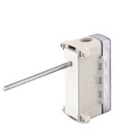
BAPI duct sensors mount through a circular penetration (typically 32 mm diameter) in the duct wall, secured with a flanged housing and self-tapping screws into the duct sheet metal. The sensing probe extends into the duct airstream. Access for installation and maintenance requires a clear working space adjacent to the duct penetration — confirm that the selected mounting location is accessible after the duct is insulated, and that any insulation jacket can be locally removed and reinstated without damaging the sensor wiring.
Application-specific mounting location guidance:
Verify duct air velocity at the installation point against the sensor's rated maximum. Most BAPI duct sensors are rated for airstream velocities up to 10–15 m/s. At velocities above this, mechanical fatigue of the probe and errors from velocity pressure effects on the sensing element may reduce long-term reliability and accuracy. At very low velocities (below 0.5 m/s), response time may be extended due to limited convective airflow past the sensing element.
The following selection logic covers the most common HVAC and BAS applications for BAPI sensors. Confirm output type compatibility with the BMS analogue input or field bus architecture before placing an order — this is the most common source of ordering errors and cannot be corrected in the field without sensor replacement.
For applications not covered by the above, or where there is uncertainty about the correct BAPI product for a specific BMS input type or protocol configuration, contact Controls Traders for technical selection support. The Controls Traders team can advise on current BAPI product availability, lead times for non-stock configurations, and compatibility with major BMS platforms installed in the Australian market.
A combination sensor in a single housing reduces installation time and wiring cost, and avoids the problem of parameters being measured at different locations in the zone — which can introduce inconsistencies in data interpretation. Where CO₂, humidity, and temperature all need to be monitored in a given zone, a combination sensor is typically the better choice for both cost and data quality reasons. Use separate sensors only when different parameters genuinely need to be measured at different locations — for example, a duct humidity sensor at the AHU to control supply humidity, combined with a wall CO₂ sensor in the occupied zone for DCV. A combination sensor in that scenario would measure supply duct conditions for humidity and zone conditions for CO₂, which are incompatible measurement requirements.
For individual zone control in a VAV system, wall-mount CO₂ sensors in each zone with 0-10 V or 4-20 mA output to the local VAV controller are the standard approach — the zone controller reads CO₂ and adjusts the VAV damper position directly. Where the BMS is managing DCV centrally rather than at the zone controller level, BACnet MS/TP sensors reduce analogue input count significantly: each sensor appears as a BACnet device on the RS-485 field bus, and the BMS reads CO₂ (and temperature and humidity if present) as standard BACnet Analogue Input objects. Contact Controls Traders for advice on the best BAPI model for your specific zone controller type and BMS platform.
For analogue voltage output sensors (0-10 V), three conductors are needed: 24 VAC/DC power supply positive, signal output (wired to BMS analogue input channel), and power/signal common. For 4-20 mA two-wire loop-powered sensors, only two conductors are needed — the supply and the return, which carries the current signal; the BMS analogue input provides the loop supply voltage. For BACnet MS/TP or Modbus RTU sensors, use a screened twisted-pair cable for the RS-485 bus, connecting data (+), data (−), and cable screen to the sensor terminal block. Observe bus termination requirements: terminate the RS-485 bus at both physical ends with the specified termination resistor value (typically 120 Ω), and ensure all devices on the bus share a common reference (signal ground). Confirm addressing requirements — BACnet MS/TP devices require unique MAC addresses in the range 1–127 for field devices, while Modbus RTU devices require unique slave addresses in the range 1–247.
BAPI capacitive polymer humidity sensors are typically rated at ±3% RH accuracy at 25°C across the 10–90% RH range. At the extremes of the measurement range — below 10% RH or above 90% RH — accuracy may be slightly reduced, though these extremes are rarely encountered in normal commercial HVAC operation. In practice, HVAC humidity control setpoints are typically 40–60% RH for comfort control and 30–65% RH for IAQ compliance, well within the range where ±3% RH accuracy is fully maintained. For critical process applications requiring tighter humidity accuracy — pharmaceutical cleanrooms, certain laboratory environments — confirm with Controls Traders whether a higher-accuracy sensor grade is appropriate.
Yes. BAPI offers BACnet MS/TP (RS-485 physical layer) as an output option across their range of combination and standalone CO₂, humidity, and temperature sensors. BACnet MS/TP sensors connect to the BMS's RS-485 field bus alongside other BACnet field devices, with each sensor appearing as a BACnet device presenting Analogue Input objects for each measured parameter — CO₂ concentration, relative humidity, and temperature as applicable. BAPI also offers Modbus RTU output as an alternative for systems using Modbus-based controllers, sub-meters, or data loggers where BACnet is not available or where the system integrator prefers Modbus. Confirm the required protocol and output configuration with Controls Traders before ordering, as factory configuration is required for digital output variants.

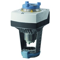
Damper actuators convert an electrical control signal into a mechanical rotation to position an air damper blade or array. In an air handling unit, damper actuators control the mix of outdoor, return, and relief air — determining how much conditioned return air is recirculated and how much fresh outdoor air is introduced. In a VAV system, they modulate the primary air damper within each terminal unit to regulate supply airflow to each zone. Selecting the correct actuator — in terms of torque output, spring-return requirement, and control signal type — is fundamental to reliable system operation across the life of the building.
The consequences of poor actuator selection are concrete and costly. An undersized actuator cannot develop sufficient torque to fully close a damper against system static pressure, allowing uncontrolled air leakage and rendering the control sequence ineffective. An oversized actuator on a lightweight VAV damper blade may distort the shaft or blade over time. Incorrect fail-safe selection — specifying a non-spring-return actuator where spring-return is required — creates freeze risk on chilled water coils and hot water coils in cold climates, or ventilation failures that may breach AS 1668.2 requirements. The guidance below covers the selection and sizing process for the most common Australian commercial HVAC applications.
Damper actuators are broadly categorised by their control signal type and by whether they include a spring-return fail-safe mechanism. The table below summarises the main types and their typical applications in commercial HVAC.
| Actuator Type | Spring Return | Fail-Safe | Typical Applications |
|---|---|---|---|
| On/off (2-position), spring return | Yes | Closes or opens on power loss | OA dampers, exhaust/relief dampers, smoke dampers |
| Floating (3-point), spring return | Yes | Yes | VAV boxes, mixing boxes, smaller AHU dampers |
| Modulating (0–10V or 4–20mA), spring return | Yes | Yes | OA dampers on AHUs requiring proportional control, mixed-air control |
| Modulating, non-spring return | No | Holds last position | VAV boxes, supply/return dampers where fail-safe is hold position |
| Smoke/fire rated | Yes (spring return) | Mandatory fail-safe | Fire/smoke dampers per AS 1668.1 |
Note: This article focuses on damper actuators for air-side control. For valve actuators on chilled water, hot water, or steam services, see the related guide to Siemens actuator series.
Outdoor air (OA) damper: The OA damper modulates or positions to control the volume of outdoor air entering the AHU. In most climate-controlled Australian buildings, the OA damper must fail closed — closing on loss of power prevents uncontrolled introduction of cold outdoor air in winter (freeze risk on chilled water coils and heating coils) and hot, humid air in summer. A spring-return actuator in the normally-closed (NC) configuration is required. The motor is energised to open the damper; on power loss, the spring drives it closed. AS 1668.2 minimum outdoor air requirements must still be achieved when the system is operational — the spring-return fail-safe addresses shutdown conditions only.
Return air (RA) damper: In an AHU with a mixing box, the return air damper is typically modulated in opposition to the OA damper — as the OA damper opens, the RA damper closes proportionally, and vice versa. The fail-safe direction depends on system design. A normally-open (NO) spring-return configuration (spring drives to fully open on power loss) is common, as it ensures return air continues to flow and prevents excessive negative pressure in the building when the AHU trips.
Relief and exhaust dampers: Provide a pressure relief path for excess supply air when the OA damper opens significantly. A normally-open (NO) spring-return actuator is frequently specified so that the building can relieve pressure even when the relief path control fails. Confirm the required fail-safe direction with the system designer based on the building pressurisation strategy.
Smoke and fire dampers: Actuators for smoke and fire dampers must comply with AS 1668.1 and AS 1851. Spring return to the closed position is mandatory — there is no alternative. Actuators must also provide auxiliary switch feedback (proof of closure) for fire control panel integration. Some dampers use a fusible link release mechanism rather than an actuator for thermal actuation — confirm the specification with the fire engineer before ordering.
A VAV terminal unit uses a single modulating actuator to position the primary air damper blade, typically a round damper within a circular duct section of 100–400 mm diameter. The control sequence is straightforward: as zone temperature rises above cooling setpoint, the VAV controller opens the primary air damper to increase cold supply airflow. As the zone reaches setpoint, the damper closes toward its minimum position, which must maintain minimum ventilation air rates per AS 1668.2. Actuators that do not reliably drive to the minimum position risk ventilation non-compliance.
The fail-safe requirement for VAV box dampers is generally less stringent than for AHU OA dampers. In most commercial applications, the VAV box damper can remain in the last commanded position on power loss — the consequence is typically zone overcooling or underheating, both of which are recoverable when power is restored. However, for spaces where uncontrolled airflow is a safety concern — data centres requiring precise cooling, neonatal units, operating theatres — the fail-safe direction must be confirmed with the mechanical engineer during design, and spring-return actuators may be required.
The torque required for VAV box dampers is relatively low (0.5–5 Nm for most round damper sizes), making compact actuator models purpose-designed for VAV applications the appropriate choice. High-cycle applications such as demand-controlled ventilation (DCV) with CO₂-based reset require actuators with a high cycle rating — verify the manufacturer's published cycle life before specifying. For Belimo actuators, the LM series is designed specifically for VAV terminal unit mounting with a compact envelope and direct-to-shaft clamp.
Correct actuator torque sizing prevents both undersizing (actuator failure, inability to fully close) and oversizing (unnecessary cost, oversized physical footprint). The basic sizing method is:
Required actuator torque (Nm) = Damper area (m²) × Specific torque (Nm/m²) + 25% safety margin
Specific torque values vary with damper blade type and seal quality. The table below provides conservative estimates suitable for sizing when the damper manufacturer's data is unavailable.
| Damper Type | Specific Torque (Nm/m²) |
|---|---|
| Standard parallel-blade, low leakage | 8–12 |
| Opposed-blade, standard | 10–14 |
| Low-leakage blade seals (knife-edge or foam) | 14–20 |
| High-performance or tight-closing | 18–25 |
Worked example: A 1.0 m² opposed-blade OA damper with standard seals: 1.0 m² × 12 Nm/m² = 12 Nm; plus 25% safety margin = 15 Nm. Select the next actuator size above 15 Nm — typically 20 Nm in most product ranges.
Always cross-reference against the damper manufacturer's published torque specification when available. Manufacturer-published values account for the actual blade geometry, seal type, and bearing friction of that specific damper model, making them more accurate than the generic values above. The generic table is a suitable starting point when manufacturer data is not yet available during early design.
For systems with multiple damper blades driven by a single actuator (a common arrangement on large louvre damper arrays using interconnected linkage), confirm that the linkage mechanism does not introduce additional friction losses that would increase the required torque beyond the sum-of-individual-blade calculation.
On/off (2-position): Two-wire control from a BMS digital output or thermostat. The actuator moves to full-open or full-closed on command. This is the simplest and most reliable configuration, with the lowest commissioning overhead. It is appropriate for OA dampers that only need fully open or closed positions — for example, night setback (damper closed when AHU is off), economiser lockout (damper closed when outdoor conditions are unfavourable), or simple ventilation applications. It is not suitable where proportional air volume control is needed.
3-point floating (pulsed open/close): Three wires — open command, close command, and common. The BMS sends an open pulse or a close pulse; the actuator moves in the commanded direction at its rated rotation speed until the pulse stops or the actuator reaches the end of travel. Position is not directly measured; the BMS estimates position from pulse timing. Common on VAV boxes and simple mixing box applications where precise position accuracy is not critical. Suitable for slower-moving, non-critical applications. Not recommended where precise air volume control or tight position accuracy is required.
0–10V modulating: Four wires — power supply, common, control signal, and optional 0–10V position feedback output. Actuator shaft position is directly proportional to input voltage: 0V corresponds to 0° (typically closed), 10V to 90° (typically fully open), with intermediate voltages commanding intermediate positions. This is the preferred signal type for AHU mixing box control and precise VAV applications. The BMS can track actual actuator position via the feedback signal and detect mechanical failures (actuator not reaching commanded position).
4–20mA: Functionally equivalent to 0–10V modulating but uses a current-loop signal. Preferred for long cable runs where voltage drop on 0–10V signals would introduce positioning error. Less common as a direct actuator input than 0–10V; verify availability in the required actuator model before specifying. The BMS output card must also support 4–20mA output.
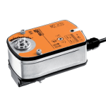
Belimo is a market-leading manufacturer of damper actuators for commercial HVAC. The product range covers compact VAV actuators through to large AHU actuators, with spring-return and non-spring-return variants across the range. The LM series (2–5 Nm) is designed for VAV terminal unit mounting; the NM series (4–10 Nm) covers medium-duty mixing box and AHU applications; the AM series (15–20 Nm) and GM series (35–40 Nm) serve larger AHU louvre dampers. Belimo actuators feature a direct-mount shaft clamp that attaches to the damper blade shaft without levers or linkages, reducing mechanical complexity and installation time. Many models include DIP-switch or rotary selector for control type selection on-site, mechanical override for manual positioning without power, and a built-in position indicator. Visit the Belimo product range or see the detailed model number guide at Belimo model numbers explained.
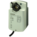
Siemens damper actuators are available in the SSA series for AHU and general HVAC damper applications (torque range 3–45 Nm across variants), and the SAS series purpose-designed for VAV terminal unit mounting. The SSA series offers an extensive range of control variants including spring-return and non-spring-return, on/off, floating, and 0–10V modulating. For a detailed guide to Siemens actuator series and model variants, see the Siemens actuator series guide. Browse the full Siemens product range available through Controls Traders.
Contact the Controls Traders team for actuator selection support, project-specific sizing advice, or to confirm stock availability for your project schedule.
Direct-drive mounting: Most HVAC damper actuators use a direct-drive clamp that attaches directly to the damper blade shaft — typically a 10–14 mm round or 10 mm square shaft. No linkages, levers, or crank arms are required for standard applications. Ensure the actuator mounting bracket is rigidly fixed to the damper frame or AHU casing. Flex in the mounting plate transmits vibration into the actuator gear train and leads to hunting behaviour in modulating applications and accelerated mechanical wear.
Span and zero adjustment: Most modulating actuators include rotary or DIP-switch adjustments for the input signal span (0–10V, 2–10V, 0–5V) and direction of rotation (clockwise or counter-clockwise for the fully open position). Set these to match the BMS analogue output range and the damper's open-direction before commissioning. An incorrectly set direction of action will cause the damper to close when commanded open — a fault that is easy to miss if visual access to the damper blades is limited.
Rotation angle: Standard HVAC damper rotation is 90°. Some actuators offer an adjustable rotation angle (e.g., 0–95° or adjustable via end stop) to compensate for damper blade travel less than 90°, or to accommodate a mechanical stop position. Confirm the actual damper travel angle from the damper manufacturer's specification before setting the actuator travel limit.
Yes, in almost all Australian commercial HVAC applications. AS 1668.2 and standard engineering practice require the OA damper to close on loss of power or control signal — a normally-closed (NC) configuration — to prevent uncontrolled outdoor air entering the system. In cold climates or where freeze protection of chilled water and heating coils is a concern, this is a safety requirement as well as an energy measure. Relief and exhaust dampers may be normally-open (fail to open on power loss) depending on the system design and the building pressurisation strategy — confirm the required fail-safe direction with the mechanical engineer for each specific application.
Multiply the damper area (m²) by the specific torque for your damper type — typically 8–20 Nm/m² depending on blade type and seal quality — then add a 25% safety margin. For example, a 0.9 m² parallel-blade OA damper with standard seals: 0.9 × 10 Nm/m² = 9 Nm, plus 25% margin = 11.25 Nm; select an actuator rated at 12 Nm or above. If the damper manufacturer publishes a torque specification, use that value as the primary sizing input — it will be more accurate than the generic Nm/m² approach because it accounts for the actual blade geometry, seal compression force, and bearing friction of that specific damper model.
For most VAV box applications, 0–10V modulating is the preferred control signal. It allows continuous proportional control that keeps zone temperature stable without the dead-band overshoot and hunting behaviour associated with 3-point floating control. 0–10V also allows the BMS to monitor actual actuator position via the feedback output, which assists commissioning and fault detection. If the VAV controller only provides a pulsed floating output, 3-point floating is acceptable — but confirm the controller output type with the BMS engineer before ordering actuators, as changing the control type after installation requires a different actuator variant.
Not without checking compatibility first. The actuator shaft clamp must match the damper blade shaft diameter and profile — common sizes are 10 mm round, 12 mm round, 12.7 mm round, and 10 mm square, but non-standard shaft sizes exist on older or imported dampers. The actuator body dimensions must also fit the available space around the damper frame, as larger torque actuators are physically larger. Most Belimo and Siemens actuators specify compatible shaft dimensions and available adaptor kits in their datasheet. For replacement projects on existing installations, inspect the actual shaft size and mounting arrangement before ordering, as the original actuator may have been supplied with a manufacturer-specific mounting bracket that is not carried in the replacement actuator's standard kit.
Not always. While many VAV boxes accept standard 10 mm round or 10 mm square shaft actuators with a universal clamp, some manufacturers use proprietary shaft profiles, non-standard shaft diameters, or require specific mounting brackets that only accept their own branded actuator. Belimo and Siemens both publish lists of compatible VAV box models for their respective actuators, including the adaptor kits required for specific boxes. When replacing actuators on existing VAV boxes, confirm the shaft size, shaft profile, and mounting arrangement by direct inspection of the installation before ordering replacements — do not rely on the original project documentation alone, as installed actuators may already have been replaced with a different model.

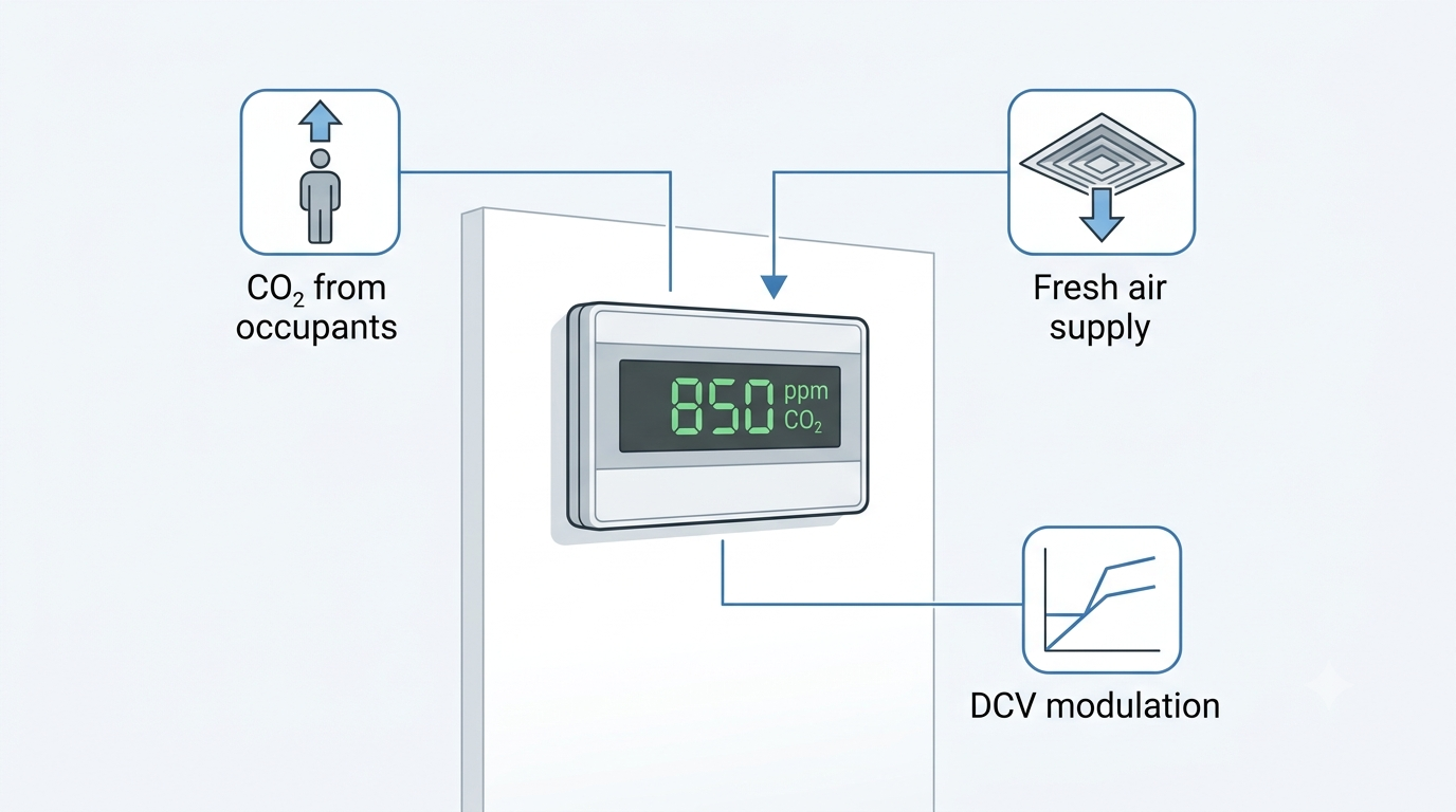
Ventilation systems sized for peak occupancy deliver far more outdoor air than necessary during periods of low or variable occupancy. A conference room designed for 40 people receiving full design airflow when only four people are present wastes substantial energy — the HVAC system overconditions outdoor air for no occupant benefit. Demand-controlled ventilation (DCV) addresses this by using CO₂ concentration as a proxy for occupancy, increasing outdoor air supply when CO₂ rises above a setpoint and reducing it when the space empties. CO₂ sensors are the measurement backbone of any DCV system. This guide covers sensor technology, placement strategies, calibration, output options, and selection criteria relevant to Australian commercial HVAC practice.
DCV is recognised in AS 1668.2 (the Australian Standard for mechanical ventilation in buildings) and is supported under the National Construction Code (NCC) as a strategy for achieving required minimum outdoor air rates while reducing energy consumption during variable occupancy. In practice, correctly commissioned DCV systems consistently deliver measurable reductions in both fan energy and conditioning load — provided the CO₂ sensors are correctly selected, placed, and maintained.
CO₂ is produced by human respiration at a rate of approximately 0.3 L/min per person at rest, rising with physical activity. Outdoor air contains approximately 420 ppm CO₂ as of the current 2024 baseline — elevated slightly from the 400 ppm figure used in older references. As occupancy increases in an enclosed space, CO₂ concentration rises above that ambient baseline. The rate of rise depends on the number of occupants, their metabolic rate, the volume of the space, and the outdoor air supply rate.
ASHRAE 62.1-2022 acknowledges CO₂ monitoring as a method for demand-controlled ventilation. A setpoint of 1,000 ppm is widely used as the upper threshold — representing the approximate equilibrium CO₂ level when ventilation is provided at the ASHRAE 62.1 person-based rate for typical office occupancy. The differential between the 420 ppm outdoor baseline and the 1,000 ppm upper setpoint provides approximately 580 ppm of working range for proportional control. An important qualification: CO₂ is an indicator of occupancy and metabolic load, not a direct measure of all indoor air quality parameters. It does not indicate elevated VOC, formaldehyde, particulate matter, or humidity. DCV based on CO₂ is appropriate for spaces where occupant-generated CO₂ is the primary driver of ventilation need — offices, conference rooms, classrooms, auditoriums, and gymnasiums. It is not appropriate as a standalone ventilation control strategy in kitchens, laboratories, car parks, or spaces with significant non-occupant-related pollutant sources.
Non-Dispersive Infrared (NDIR) is the standard CO₂ sensing technology in all HVAC-grade sensors. Alternative technologies — including electrochemical cells and metal oxide semiconductor (MOS) sensors — are occasionally found in low-cost consumer devices but are not appropriate for commercial HVAC DCV applications due to poor long-term stability, cross-sensitivity to other gases, and limited service life.
The NDIR operating principle involves four components:
NDIR has three significant advantages for HVAC applications: accuracy of ±50 ppm at calibration is readily achievable; the NDIR optical cell has no chemical reaction and does not deplete over time, giving service lives of 10–15 years; and the technology is stable across the humidity and temperature ranges encountered in occupied building environments.
Most HVAC CO₂ sensors use Automatic Baseline Calibration (ABC), sometimes labelled as self-calibration or background calibration. The ABC algorithm assumes that at some point during a regular cycle — typically 7–14 days — the monitored space will be unoccupied and the sensor will be exposed to outdoor air at near-ambient CO₂ concentration. Over each cycle, the algorithm records the minimum CO₂ reading and, after several cycles, uses a statistical average of those minima to reset the sensor's zero baseline.
ABC is effective and low-maintenance for the overwhelming majority of commercial HVAC applications — offices, schools, retail, conference facilities — where spaces are reliably unoccupied overnight and on weekends. The algorithm typically maintains calibration within ±50 ppm across the sensor's service life in these conditions.
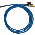
ABC fails in continuously occupied spaces such as certain hospital wards, 24-hour call centres, some manufacturing and data centre environments, and other facilities that are never genuinely unoccupied. In these applications, commission sensors with manual calibration capability and calibrate against a known reference gas — 400 ppm reference gas in nitrogen is the standard for zero calibration. Alternatively, relocate the sensor to an adjacent space that is genuinely unoccupied overnight for its calibration cycle. Schedule annual manual verification in any application where there is uncertainty about whether the space achieves full unoccupied periods.
Two primary mounting strategies are used in DCV systems, each with distinct advantages depending on the system architecture.
Wall (zone) sensors are mounted in the occupied space at breathing height — 1.2–1.5 m above finished floor level. They directly measure the CO₂ concentration in the zone being controlled, providing the highest accuracy for individual zone DCV. Wall sensors are best practice for single VAV box control, individual room DCV, and any application where occupancy varies substantially between adjacent zones. Multiple zone sensors are required in multi-zone systems — one per independently controlled zone. Common placement errors to avoid: proximity to supply air diffusers (dilution effect will cause the sensor to underread), proximity to operable windows or doors (infiltration from corridors or outdoors will depress the reading), and proximity to return air grilles (elevated local CO₂ adjacent to the grille is not representative of the zone average).
Duct return sensors are mounted in the return air duct serving the air handling unit (AHU), or in the AHU return air section itself. They measure a blended CO₂ concentration representing all zones returning air to that AHU. A single duct sensor per AHU replaces the need for individual zone sensors and can be used to control the AHU's outdoor air damper directly. The trade-off is accuracy: the mixed-air reading averages occupancy across all zones, so a high-occupancy conference room returning air to the same AHU as an empty office will have its occupancy signal diluted. Duct return sensors are most appropriate for large open-plan areas with relatively uniform occupancy distribution — not for buildings with a mix of high and low occupancy rooms on the same AHU.
| Placement Option | Best Use Case | Measurement Accuracy | Installation Complexity |
|---|---|---|---|
| Wall (zone) sensor | Single zone or individual room control | Highest — direct zone measurement | Higher (one sensor per controlled zone) |
| Duct return sensor | Central AHU serving uniform occupancy | Lower — averaged mixed-air reading | Lower (one sensor per AHU) |
| Zone + duct combination | Large buildings with mixed space types | Comprehensive | Highest cost and complexity |
A proportional DCV control strategy using CO₂ as the process variable is straightforward to implement in any BMS capable of reading an analogue input. The following setpoints are typical for Australian commercial office applications under AS 1668.2 design criteria:
The CO₂ sensor output — typically 4-20 mA or 0-10 V scaled to 0–2,000 ppm — is wired to a BMS analogue input. The BMS modulates the outdoor air damper actuator using a PID control loop with CO₂ concentration as the process variable and outdoor air damper position as the control output. Wind-up protection and minimum position overrides are important configuration considerations: the outdoor air damper must never close below the hygienic minimum regardless of CO₂ level, and the control loop must be tuned to the relatively slow time constant of zone CO₂ response (typically 5–20 minutes for a well-mixed office zone).
The energy benefit of DCV is most pronounced in spaces with highly variable occupancy. Conference rooms, auditoriums, lecture theatres, and gymnasium spaces are frequently designed for peak occupancy loads that are achieved only a fraction of the time. DCV in these spaces can reduce HVAC energy consumption by 15–30% compared to constant-volume outdoor air systems, with the majority of savings occurring in the conditioning energy required to treat outdoor air (cooling, dehumidification, or heating depending on climate and season).
CO₂ sensor output type must match the BMS or controller input available at the installation. Three output formats are in common use in Australian commercial BAS practice:
Specifying CO₂ sensor accuracy correctly requires understanding both the initial calibration accuracy and the long-term drift behaviour. Typical HVAC-grade NDIR CO₂ sensor specifications are:
| Parameter | Typical Specification |
|---|---|
| Measurement range | 0–2,000 ppm (HVAC DCV) or 0–5,000 ppm (industrial / safety monitoring) |
| Accuracy at calibration | ±50 ppm ± 3% of reading (e.g., ±80 ppm at 1,000 ppm reading) |
| Long-term drift (with ABC) | <20 ppm per year, corrected by ABC algorithm |
| Temperature compensation range | 0–50°C (automatic); some models to 60°C for duct applications |
| Operating humidity | 0–95% RH, non-condensing |
| Rated service life | 10–15 years (NDIR optical cell) |
Temperature compensation is particularly important for duct-mount sensors, where the air temperature may differ substantially from the ambient room temperature, and where rapid airflow can affect the thermal equilibrium of the sensor cell. Verify that the sensor's stated temperature compensation range covers the expected duct temperature at the installation point — in mixed-air duct sections in Australian climates, temperatures between 10°C and 40°C are common depending on season and system configuration.
BAPI (Building Automation Products Inc.) offers a comprehensive range of wall-mount and duct-mount CO₂ sensors for HVAC DCV applications, available in Australia through Controls Traders. The BAPI CO₂ sensor range includes standalone CO₂ units for straightforward DCV applications as well as combination sensors integrating CO₂ with relative humidity and temperature measurement in a single housing — an arrangement that reduces wiring and installation time significantly where all three parameters are required in a zone.
BAPI CO₂ sensors support multiple output options including 4-20 mA, 0-10 V, BACnet MS/TP, and Modbus RTU, making them compatible with all major BMS platforms used in Australian commercial and industrial buildings. Combination sensors with digital outputs are particularly efficient in multi-zone systems, where a single RS-485 bus can carry CO₂, humidity, and temperature data from multiple sensors to the BMS without the wiring overhead of individual analogue inputs per parameter. For sensor selection, product availability, and technical assistance, contact the Controls Traders team.
1,000 ppm is the widely used upper setpoint, based on ASHRAE 62.1 guidance and representing approximately the equilibrium CO₂ level when ventilation is provided at the standard person-based rate for office occupancy. A proportional control band of 700–1,000 ppm is common, where the outdoor air damper modulates from minimum to maximum outdoor air as CO₂ rises through this range. Some projects specify tighter setpoints — 800–850 ppm upper limit — where higher indoor air quality targets are required. Confirm the setpoint strategy with the project mechanical specification and the relevant authority in your jurisdiction, as NCC DtS provisions and Green Star or NABERS credits may impose specific requirements.
Sensors with Automatic Baseline Calibration (ABC) self-calibrate by periodically resetting their zero to the minimum reading over a 7–14 day cycle, assuming the space is unoccupied during that period. In genuinely variable-occupancy spaces, ABC typically maintains calibration within ±50 ppm over multiple years without manual intervention. For spaces that are never fully unoccupied, schedule annual manual calibration using 400 ppm reference gas. Sensors that are consistently reading more than 100 ppm above a calibrated reference despite ABC correction, or that have exceeded the manufacturer's stated service life of 10–15 years, should be replaced rather than recalibrated.
Wall-mount (zone) sensors in the occupied space provide the most accurate reading for individual zone DCV — they measure actual occupant CO₂ without the averaging effect of mixing with air from adjacent zones. Duct-return sensors are suitable for central AHUs serving large, relatively uniform occupancy spaces, where a mixed-air reading is an acceptable proxy for zone-level CO₂ concentration. For conference rooms, classrooms, and other variable-occupancy rooms, wall-mount sensors in each room give significantly better control performance and are recommended where budget permits. A duct return sensor can still be used as a secondary check or system-level override in combination with zone sensors.
NDIR CO₂ sensors are designed specifically to measure CO₂ concentration by targeting the 4.26 μm absorption wavelength; they do not measure VOCs, formaldehyde, particulate matter, carbon monoxide, or other indoor air quality parameters. For spaces where multiple pollutant sources exist — commercial kitchens, laboratories, print rooms, car parks — DCV based on CO₂ alone is insufficient to ensure adequate ventilation for all contaminants. In those applications, CO₂ monitoring may still be included as part of a broader IAQ strategy, but ventilation rates must not be reduced below the level required to dilute non-occupant-generated pollutants to safe concentrations.
NDIR CO₂ sensors typically carry a rated service life of 10–15 years. Unlike electrochemical sensors, which rely on a chemical reaction that gradually depletes a reagent, the NDIR optical cell operates without a consumable element — degradation occurs slowly through contamination of the optical surfaces and gradual ageing of the infrared source. Sensors that are consistently reading more than 100 ppm above a calibrated reference after ABC correction, or that have exceeded the manufacturer's stated service life, should be scheduled for replacement as part of building maintenance planning. Record sensor installation dates in the BMS or asset register to facilitate planned replacement programmes.